
Installation guide


Installing Custom Cable Systems
890 USE 100 00
237
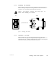
V At any connector, measure the resistance between pins 2 and 3 (the
signal pins). Measure this at the connector’s external pins, not at
its internal wiring terminals. This should be in the range of 60 to
80 ohms, which includes the cable wire resistance.
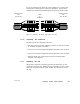
V At one end connector, connect a jumper between pin 2 (a signal pin)
and pin 1 (the shield pin). At the other end connector, check for
continuity between pin 2 and pin 1. Continuity should be present.
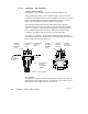
V Leaving the meter connected as above, remove the jumper. Again
check the continuity between pin 2 and pin 1. It should be an open
circuit.
V At any connector, check the continuity between pin 1 and the plant
ground point on the local site panel or frame. It should be an open
circuit.
If your checks do not agree with these results, inspect the cable and
connectors for damage or miswiring, and correct the condition.