
Installation guide


236 Installing Custom Cable Systems
890 USE 100 00
D .10 Checking the Cable Installation
This section describes how to visually inspect the cable and check its
endtoend electrical continuity.
D .10.1 Inspecting the Cable Installation
V The cable runs should agree with the physical and electrical
protection requirements in Chapter 2.
V The cable runs should agree with the network cable routing
diagram as described in Chapter 2.
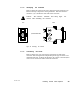
V Each inline drop site should have two cables, connected to one
inline connector (dark grey).
V The two end drop sites on each section of the network should each
have one cable, connected to a terminating connector (light grey).
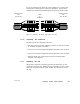
V The cable direction (left or right) into each connector should be
correct according to the type of device to be installed at each site.
V Each connector should be tightly secured to its cable(s) by a cable
tie.
V Adequate strain reliefs should be installed on the cable at each
drop.
V All identification labels should be in place and properly marked.
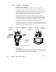
D .10.2 Checking the Cable Continuity
V These continuity checks are applicable to cable installations that
use only the components described in this Appendix. These checks
do not apply to installations that use the tap and drop cable
components described in Chapter 5.
V Before checking continuity, all cable connectors should be
disconnected from the network devices.