
Installation guide


Installing Custom Cable Systems
890 USE 100 00
231
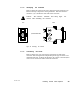
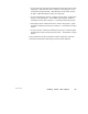
If you are connecting an inline site, refer to Figure 101. Connect the
second cable to the connector as shown in the figure. Use the same
methods for connecting and checking the wiring as for the first cable.
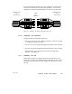
1
2
3
CABLE TO LEFT
FOR
984385, 485
CABLE TO RIGHT
FOR
984685, 785
WIRE
TERMINAL
TO
1
2
3
Figure 101 Connecting the Second Cable (Inline Sites Only)
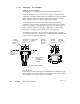
D .7.6 Inspecting the Connection
Visually inspect the completed connection:
V The wire colors are correct: White at terminal 1, Bare at terminal
2, and Blue or Black at terminal 3
V All wires are routed straight through the channels in the connector
V All wires are inserted completely into the channels in the connector
V The bare drain wire is not frayed, and is not touching either
terminal 1 or terminal 3.
D .7.7 Replacing the Cap
When all the wires are in correctly placed in the connector, you can
replace the connector cap. Taking care not to dislodge any wire, fit the
connector cap to the connector body. Tighten the cap screw to secure
the cap.