
Installation guide


230 Installing Custom Cable Systems
890 USE 100 00
1
2
3
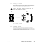
CABLE TO LEFT
FOR
984385, 485
CABLE TO RIGHT
FOR
984685, 785
WIRE
TERMINAL
TO
WIRE
PRESS EACH
WHITE WIRE AND
WIRE FULLY INTO
ITS TERMINAL
LAY EACH
BARE DRAIN
WIRE INTO
ITS GROOVE
WIRE
1 INCH
(2.5CM)
1 INCH
(2.5CM)
BLUE OR BLACK WIRE
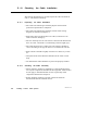
Figure 100 Connecting the W ires
Refer again to Figure 100. Note the wire color that will connect to each
terminal. The white wire will connect to terminal 1, the bare drain
wire to terminal 2, and the blue or black wire to terminal 3.
To connect a white, blue, or black wire, lay it across the top of its
terminal with the cable’s outer jacket approximately one inch (2.5 cm)
away from the connector. Using the connector cap as a tool, press the
wire fully into its terminal. When the wire is fully inserted, it will
bottom into its terminal as shown in Figure 100.
After connecting each wire, check continuity between the wire
conductor and terminal. Check this with an ohmmeter between the
exposed end of the wire and the terminal.
Lay the drain wire over terminal 2 (the center contact area). Do not
allow the wire to contact any other terminal. Make sure the drain wire
is into its groove in the connector body as shown in Figure 100.