
Installation guide


Installing Custom Cable Systems
890 USE 100 00
229
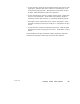
D .7.4 Identifying the Terminals
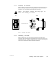
Refer to Figure 99. Remove the screw that secures the connector cap.
Remove the cap to expose the wiring terminals. Note the terminal
numbers (1, 2, 3) marked on each side of the connector.
Caution: The connector terminals have sharp edges. Use
caution when handling the connector .
TOP SIDE
(COVER REMOVED)
Figure 99 Identifying the Terminals
D .7.5 Connecting the W ires
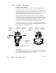
Refer to Figure 100. All wires will be routed into one side of the
connector. The wiring direction depends upon the type of device to be
installed at the site, as shown in the figure. If a device is not listed, the
wires can be routed into either side of the connector.