
Installation guide

228 Installing Custom Cable Systems
890 USE 100 00
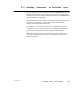
You will also need to know which type of network device (type of
Modicon 984 controller or other device) is to be installed at each point
on the cable. The connector wiring direction will depend on the type of
device installed.
D .7.2 Overview of the Connector Installation
Each connector requires six kinds of action:
V Preparing the cable
V Identifying the connector terminals
V Connecting the wires
V Inspecting the connection
V replacing the cap
V Completing the connection
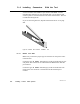
D .7.3 Preparing the Cable
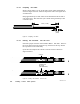
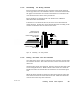
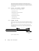
Remove 3 in (7.5 cm) of the cable’s outer jacket and shields as shown in
Figure 98 below. This will expose the cable’s two signal wires and drain
wire.
Strip approximately 1/4 in (6 mm) of the insulation from the end of
each signal wire. This will allow you to check wiring continuity to the
connector’s pins.
3.0 IN (7.5 CM)
0.25 IN
(6 MM)
Figure 98 Preparing the Cable