
Installation guide

Installing Custom Cable Systems
890 USE 100 00
225
D .6.9 Completing the Installation
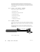
Checking W iring Continuity
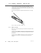
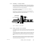
Open the tool, and remove the connector and cable. Locate pins 1, 2,
and 3 of the connector as shown in Figure 96.
Using an ohmmeter set to a lowresistance range, verify that direct
continuity (zero ohms) exists between each white wire and pin 3. Verify
direct continuity between each blue or black wire and pin 2. Verify
direct continuity between each bare drain wire and pin 1.
If an improper connection has been made, and you have already
installed one or both of the connectors at the two ends of the network
cable, it is possible to read either 60 or 120 ohms resistance between a
blue or black or white wire and its pin. Make sure you have direct
continuity (zero ohms) between each wire and its proper pin.
Verify that no continuity (an open circuit) exists between each white
wire and each drain wire. Verify that no continuity exists between each
blue or black wire and each drain wire.
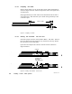
3 2 1
Continuity
from blue or
black wires
to pin 2
Continuity from
bare wires
to pin 1
Continuity from
white wires
to pin 3
Trim wires
after checking
continuity
Wiring direction
shown for
984685/785
controller.
Note:
1 2 3
Side View
Continuity
from blue or
black wires
to pin 2
Continuity
from bare
wires to pin 1
Continuity
from white
wires to pin 3
Pin View
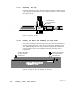
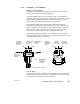
Figure 96 Checking W iring Continuity
Trim the W ires
If continuity is normal, trim the excess lengths of wire so that they are
flush with the side of the connector. If continuity is not normal, repeat
the installation procedure with a new connector.