
Installation guide

Installing Custom Cable Systems
890 USE 100 00
223
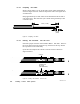
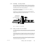
D .6.5 Determining the W iring Direction
The wires must be inserted into the connector in the proper direction
for the type of device to be installed at the site. The tool is labeled with
the proper wire direction for various network devices. Determine the
wire direction for the device at the present site.
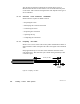
Figure 93 shows an example of the wire direction for a Modicon
984685 or 984785 controller.
If the device is not listed on the tool, the wires can be inserted from
either direction. In this case, choose the best direction according to the
manner in which the cable is routed to the device.
DRESS WIRES THIS SIDE
FOR 685/785
DRESS WIRES THIS SIDE
FOR 385/485
1 INCH
(2.5CM)
WIRES IN PLACE
(685/785 EXAMPLE)
Figure 93 Determining the W iring Direction
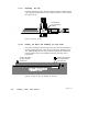
D .6.6 Placing the W ires into the Connector
One cable (three wires) will be connected to the connector at each of the
two extreme end sites. Two cables (six wires) will be connected at each
inline site.
Observing the proper wire direction, place the wires into the slots of the
tool as in Figure 93 above. Make sure the white wires are toward the
handle end of the tool and the blue or black wires are toward the pivot
end.
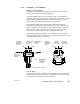
When the white and blue or black wires have been inserted, insert the
bare drain wires into the center slots of the tool. Make sure the drain
wires do not contact any other terminal.