
Installation guide

222 Installing Custom Cable Systems
890 USE 100 00
D .6.3 Preparing the Cable
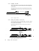
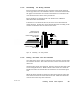
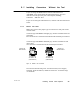
Remove three inches (7.5 cm) of the cable’s outer jacket and shields as
shown in Figure 91 below. This will expose the cable’s two signal wires
and drain wire.
Strip approximately 1/4 inch (6 mm) of the insulation from the end of
each signal wire. This will allow you to check wiring continuity to the
connector’s pins.
3.0 IN (7.5 CM)
0.25 IN
(6 MM)
Figure 91 Preparing the Cable
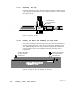
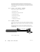
D .6.4 Placing the Connector into the Tool
Select the proper connector as described in Before You Start . Remove
the screw that secures the connector cap, and remove the cap. Retain
the cap and screw for reassembly.
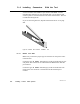
Open the tool and place the connector into the cutout as shown in
Figure 92 below.
CONNECTOR
IN PLACE
(CAP REMOVED)
CUTOUT
Figure 92 Placing the Connector into the Tool