
Installation guide

6 Introducing the Modbus Plus Network
890 USE 100 00
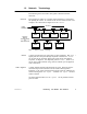
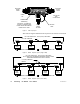
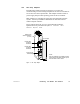
Node Any device that is physically connected to the Modbus Plus cable.
Figure 2 shows a network with seven node devices. The term applies
to any device, whether it is addressable or not. Some nodes , like
programmable controllers, have addresses and can serve as sources or
destinations for messages. The Bridge Plus is a separately
addressable node on each of its two networks. The Repeater is a node
on each of two sections, but has no address, serving only to extend the
network.
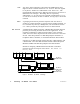
Token A grouping of bits that is passed in sequence from one device to
another on a single network, to grant access for sending messages. If
two networks are joined by a Bridge Plus, each network has its own
token that is passed only among the devices on that network.
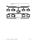
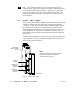
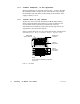
DIO Network A Distributed I/O (DIO) network is a Modbus Plus network designed
primarily for servicing I/O field devices in the application. In its
minimum configuration a DIO network consists of one controller
(CPU) and one or more drops located at remote sites near to the field
devices. Each drop consists of a DIO Drop Adapter installed in a
backplane with I/O modules, or a Terminal Block I/O (TIO) module.
In Figure 3, one DIO network contains the CPU, a DIO Adapter, and
a TIO module. Two other DIO networks consist of Network Option
Modules (NOMs) with DIO Drop Adapters and TIO modules.
Details for designing a Modbus Plus network that is intended
primarily for I/O servicing are in the Modbus Plus Network I/O
Servicing Guide.
C
P
U
N
O
M
P
S
I/O
MODULES
UP TO 64
NODES TOTAL
UP TO 64
NODES TOTAL
UP TO 64
NODES TOTAL
D
I
O
D
I
O
D
I
O
N
O
M
TIO
I/O
MODULES
I/O
MODULES
I/O
MODULES
TIO
TIO
Figure 3 Distributed I/O Network Terminology