
Installation guide

194 Message Routing
890 USE 100 00
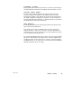
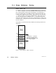
B .3 Controller Bridge Mode Routing
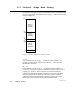
If a Modbus message is received at the Modbus port of a controller that
is set to bridge mode, the address (in the range 1 ... 255) is converted as
shown in Figure 75.
RESERVED
RESERVED
0
1
64
65
69
70
79
80
255
DIRECT
ATTACH
ADDRESS
EXPLICIT
ATTACH
ADDRESS
IMPLICIT
ATTACH
ADDRESS
Figure 75 Controller Bridge Mode Address Conversion
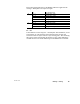
1 ... 64
If the address is in the range 1 ... 64 (Direct Attach Address), the
message is routed to the specific node address 1 ... 64 on the local
Modbus Plus network.
70 ... 79
If the address is in the range 70 ... 79 (Explicit Attach Address), it
causes the controller to access an address map table stored in a set of
holding (4x) registers. These registers are located immediately
following the Free-Running Timer Register in user logic (you must
therefore implement the Timer in your logic program). Modbus
addresses in this range thus become pointers to the routing table,
which contains ten stored routing paths for Modbus Plus.