
Installation guide


Modbus Plus Transaction Elements
890 USE 100 00
187
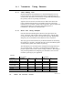
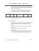
A .4.1 LLC Fields
The message contains the following LLC level fields:
Master Output Path
One byte identifying the originating node’s output path for
transmission of the message. Although each controller has one
physical port for access to the network, it maintains multiple logical
paths internally for sending and receiving messages. This allows
multiple transactions to remain queued within the controller while it
completes communications with other controllers. The controller will
reserve the specified path until its transactions on that path are
completed.
Router Counter
This field counts the number of Bridge Plus devices traversed, to
control message queueing. Messages are queued in the first bridge
only.
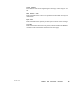
Transaction Sequence
One byte identifying the transaction between the source and
destination. Multiple messages associated with a single transaction
contain a value which remains constant while the transaction is active.
If a source initiates a message requesting data from a destination, the
returned data message will include the same transaction sequence
value. If the source initiates a message requesting data from a
destination, and then aborts the transaction before receiving the data,
the source can initiate a new message with the same destination
without waiting for returned data for the aborted transaction. The two
messages will have different transaction sequence values. When
returned data is received from the destination, the transaction
sequence value in the received message will identify the data as being
either from the aborted transaction or from the newly initiated one.
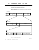
Routing Path
This field is implemented as follows:
For messages to programmable controller nodes on Modbus Plus: each
nonzero byte except the last specifies routing through a Bridge Plus to
another network. The last nonzero byte specifies the destination
controller’s node address (164).
For messages to SA85 Host Based Device nodes: each byte up to and
including the device’s node address specifies routing to the device.
Bytes following the node address byte can be used by the host
application to specify application tasks running in the host.