
Installation guide


180 Modbus Plus Transaction Elements
890 USE 100 00
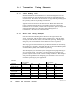
A .1.3 Data Response T ime
When a node’s application program initiates a transaction, the time
required for a data response to be returned to the application depends
upon several factors: the internal timing of the initiating node, the
token rotation and transmission timing on the network, and the
internal timing of the responding node.
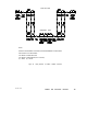
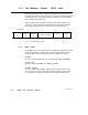
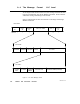
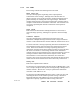
Figure 69 illustrates the elements of one READ or WRITE transaction
as it occurs in initiating and responding controller nodes. The
transaction is moving 100 registers of data. Where the times differ
between operations, the READ transaction timing is shown with an (R)
and the WRITE timing with a (W).
Timing starts when an MSTR is enabled in the initiating node. The
transaction is finished when the MSTR function’s COMPLETE output
is ON. In the case of the READ, registers will be updated in the
initiating node at that time.
The token rotation time of the network and the scan times of the
devices will usually predominate in the endtoend timing of the
transaction. The other timing elements are typically much shorter
than the token rotation and scan times. The graphs and formulas in
Chapter 3 include all of the timing elements in the diagram. You
should use the material in that chapter for predicting response times
and throughput in your network design.