
Installation guide


172 Connecting a BP85 Bridge Plus
890 USE 100 00
7.8 Reading the Network Indicators
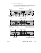
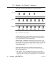
The layout of the Bridge Plus indicators is shown in Figure 67.
Modbus
Plus
Port 2
Modbus
Plus
Port 1
Power
OK
Ready
power
OK
MP
port 1
error
chan B
error
chan A
MP
port 2
error
chan B
error
chan A
BP85-000
BP85-002
power
OK
MP
port 1
error
chan B
error
chan A
MP
port 2
error
chan B
error
chan A
BP85D002
Figure 67 BP85 B ridge Plus Indicators
POWER OK illuminates when the BP85 has normal power from the
source. READY (NW-BP85-000 only) illuminates when the BP85 has
successfully completed its internal diagnostics.
ERROR CHAN A and ERROR CHAN B show the fault status on the
two cable paths for each network. If an indicator blinks momentarily, it
indicates that a message error was detected on the path. A steady ON
state indicates a hard fault either in the cable or in a node device
connected to the cable.
PORT 1 and PORT 2 show the communication status at the two
Modbus Plus network ports. Status is shown by flashing a repetitive
pattern. The patterns are:
V Six flashes/s This is the Bridge Plus’s normal operating state.
All nodes on the network should be flashing this pattern. If a port
indicator is OFF continuously, the Bridge Plus is not transmitting
at that port.