
Installation guide


170 Connecting a BP85 Bridge Plus
890 USE 100 00
7.6 Connecting the Network Cables
If the cables and connectors are not in place, install them as described
in Chapter 5 of this guide. If the network cables are not labeled,
contact the person who is responsible for the network planning and
layout before proceeding. When you have this information, connect the
cables as described below.
Caution: If the network cables are not labeled, or if you do
not have a layout diagram showing which cable is to be
connected to each connector on the Bridge Plus, you should
not connect the cables until you obtain this information. The
Bridge Plus connectors have dedicated network addresses that
you have set in the unit’ s address switches. Incorrect
connection of the cables can cause a disruption of
communication on the networks.
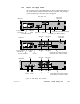
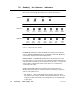
Refer to Figure 66. Connect the network cable connectors to the
connectors provided on the Bridge Plus’s rear panel. If the networks
are active, the unit’s MODBUS PLUS PORT 1 and MODBUS PLUS
PORT 2 indicators should begin flashing.
V Connecting Single-cable Units on Singlecable Networks:
If you are installing a single-cable unit (BP85-000) on networks that
have a single cable, you will have two cables to connect to your
BP85. Connect the cables to the Port 1 and Port 2 connectors. Se-
cure each connector by tightening its two screws.
V Connecting Dual-cable Units on Dualcable Networks:
If you are installing a dual-cable unit (BP85-002) on a dual-cable
network, you will have four cables to connect to your BP85. Each
network should have two cables, labeled A and B. Connect the
cables to the connectors on the BP85 rear panel. Secure each con-
nector by tightening its two screws.
V Connecting Dual-cable Units on Singlecable Networks:
If you are installing a dual-cable unit (BP85-002) on networks that
have a single cable, you will have two cables to connect to your
BP85. Connect the cables to the Port 1 A and Port 2 A connectors.
Plug two Terminating Connectors (ASMBKT185) into the Port 1
B and Port 2 B connectors. Secure each connector by tightening its
two screws.