
Installation guide


Connecting a BP85 Bridge Plus
890 USE 100 00
169
7.5.3 Before You Apply Power
Do not apply power to the BP85 until you have completed the setup of
the unit’s network address switches for both networks. The settings
will be sensed by the unit when power is applied.
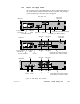
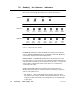
Rear Panel V iew
(Upper) MB+ port 2 address switches
+
24 VDC
Power cable
strain relief
MB+ port 2
B
MB+ port 1
B
MB+ port 2
A
MB+ port 1
A
BP85-002
BP85-000
Power cable
strain relief
MB+ port 2MB+ port 1
(Right) MB+ port 2 address switches
AC power connector
AC power
switch
(Left) MB+ port 1 address switches
AC power selector
plug and fuse
AC power selector
plug and fuse
AC power connector
AC power
switch
(Lower) MB+ port 1 address switches
GND
(Upper) MB+ port 2 address switches
(Lower) MB+ port 1 address switches
+
24 VDC
+
125 VDC
MB+ port 2
B
MB+ port 1
B
MB+ port 2
A
MB+ port 1
A
BP85D002
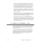
Figure 66 BP8 5 Bridge Plus Connectors