
Installation guide


168 Connecting a BP85 Bridge Plus
890 USE 100 00
7.5 Connecting the Power Cables
Caution: If y o u are replacing a Bridge Plus on an active
net w ork, the communication between the n etworks served b y
the Bridge Plus will be temporarily disabled as you disc cnnect
the old device and connect the new one. Always plan fo r an
orderly shutdown of your control process if necessary , w h ile
you replace a Bridge Plus on an active netw o rk.
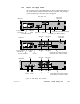
A C/DC Models
AC/DC models are supplied with a power cable of 6 ft (2 m) length for
operation from 110120 Vac or 220240 Vac singlephase power. The
cable connects to a socket on the rear panel. Grounding is through the
cable. The ac line switch is located on the rear panel. The unit
contains an ac line fuse that is accessible on the rear panel.
These models can also operate from an external 24 Vdc source. Power
connects to a socket on the rear panel. Grounding is through the cable.
The dc source must be switched and fused externally to the unit.
DC/DC M odels
DC/DC models operate from a 125 Vdc or 24 Vdc source. Power
connects to a terminal strip on the rear panel. A grounding terminal is
provided. The dc source must be switched and fused externally to the
unit.
7.5.1 Connec ting AC Power
Set the BP85 power switch to the ‘0’ (power OFF) position. Connect the
BP85 to the power source. Test the connection by setting the power
switch to ‘1’ (power ON). The POWER indicator should illuminate.
Before connecting the network cables, set the power switch to the ‘0’
(power OFF) position. The POWER indicator should not be lit.
7.5.2 Conne c ting DC Power
Set the external dc power source to OFF. Connect the BP85 to the
source. Test the connection by setting the dc power source to ON.
The POWER indicator should illuminate.
Before proceeding with the connection of the network cables, set the dc
power source to OFF. The POWER indicator should not be lit.