
Installation guide


166 Connecting a BP85 Bridge Plus
890 USE 100 00
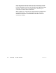
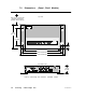
7.4 Settin g the Modbus Plus Addresses
Before you apply power to the BP85, you must set the unit’s network
addresses in two groups of switches on the unit’s rear panel.
Because the BP85 serves two networks, it has a set of port connectors
for each network and an associated group of switches for assigning the
unit’s address on each network. Figure 66 shows the switch locations.
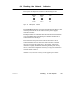
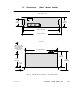
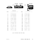
Figure 65 shows the switch setup combinations and resulting
addresses.
Set each group of switches to the BP85’s address on the network that
will be connected to the port connector. The network address will be
one higher than the binary value you set into switches 1 ... 6. Switches
7 and 8 are not used.