
Installation guide

Connecting an RR85 Repeater
890 USE 100 00
157
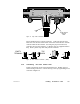
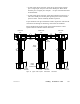
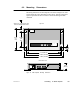
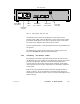
Rear Panel V iew
Power cable
connector
Power
switch
Modbus Plus
port 1 connector
Power selector
plug and fuse
Power cable
strain relief
Modbus Plus
port 2 connector
Figure 61 RR85 Repeater Rear Panel V iew
Set the main power switch on the Repeater’s rear panel to the 0
position (power OFF). Plug the Repeater’s power cable into the socket
provided on the Repeater’s rear panel. Secure the power cable under
the strain relief. Plug the cable into the power source.
Using a continuity tester, verify the Repeater chassis is grounded to the
site ground.
Set the Repeater’s main power switch to the 1 position (power ON).
The unit’s POWER OK indicator should illuminate.
6.3.3 Connecting the Network Cables
Two sections of network trunk cable should already have been run to
the Repeater site, representing the two links of the network that will be
joined by the Repeater. Each set of cables should already have a
network tap and a drop cable with connector installed. If the cables
and connectors are not in place, install them as described in Chapter 5
of this guide.
Each of the cable segments should be labeled to identify the link to
which it connects. If you are following a network layout diagram, it
should show which cable connector is to be mated to each Repeater rear
panel connector.