
Installation guide

156 Connecting an RR85 Repeater
890 USE 100 00
6.3 Installing the Repeater
Caution: If you are replacing a Repeater on an active Modbus
Plus network, the communication between the two links of the
network will be temporarily disabled as you disconnect the
old device and connect the new one. The network signal path
passes through the Repeater via its two rear panel connectors.
This path will be interrupted as you disconnect the cables
from the ports.
Always plan for an orderly shutdown of your control process
if necessary , while you replace a Repeater on an active
network.
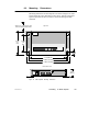
6.3.1 Mounting the Repeater
Mount the Repeater on the horizontal or vertical surface using the
guidelines described earlier in this chapter. Make sure you have proper
access to the rear panel connectors and power switch.
6.3.2 Connecting Power
The power cable supplied with the Repeater is keyed for North
American 110/120 VAC power outlets. If necessary, install a different
plug on the cable for the power source at your site.
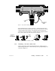
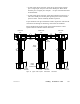
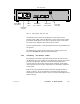
Refer to Figure 61. On the rear panel of the Repeater, set the power
selector plug to the 110/120 VAC or 220/240 VAC position for the power
source at your site. To do this, remove the power selector plug by
prying under its tab using a small screwdriver. Set the plug to the
proper voltage position as shown on the plug body, then reinsert it.