
Installation guide

Installing the Network Cable
890 USE 100 00
151
V At each node device connector, check for an open circuit between
pin 2 (a signal pin) and pin 1 (the outer shield pin). Then check
between pin 3 (a signal pin) and pin 1. An open circuit should exist
for both checks.
V At each node device connector, check the continuity between pin 1
(the outer shield pin) and the plant ground point on the local site
panel or frame. Direct continuity should be present.
If your checks do not agree with these results, inspect the cable and all
connections for damage or miswiring, and correct the condition.
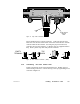
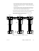
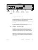
Figure 59 shows the point-to-point wiring connections for a cable
system with two end sites and one inline site.
TAP TAP TAP
END SITE END SITEINLINE SITE
TRUNK
CABLE
DROP
CABLE
PANEL
GROUND
3 1 2
PANEL
GROUND
3 1 2
PANEL
GROUND
3 1 2
TAP
GROUND
DROP
CABLE
CONNECTOR
Figure 59 Typical Cable System: Point-to-Point Connections