
Installation guide

150 Installing the Network Cable
890 USE 100 00
5.10 Checking the Cable Installation
This section describes how to visually inspect the cable and check its
end-to-end electrical continuity.
5.10.1 Inspecting the Cable Installation
V The cable runs should agree with the physical and electrical
protection requirements in Chapter 2.
V The cable runs should agree with the network cable routing
diagram as described in Chapter 2.
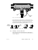
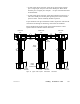
V The tap at each of the two end drop sites on each section of the
network should have its two internal termination jumpers
connected; they must be connected between the two center posts
and the W and B posts at the side of the tap opposite from the
trunk cable connection.
V The tap at each inline drop site should have its two internal
termination jumpers disconnected and removed.
V Service loops should exist on the trunk cable at each tap—service
loops should exist on each drop cable at the node device end of the
cable.
V Each tap should have the drop cable’s ground wire connected to its
grounding screw; the drop cable’s ground wire should also be
connected to the panel grounding point at the node device site.
V Adequate strain reliefs should be installed on the cable at each
drop.
V All identification labels should be in place and properly marked.
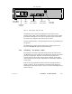
5.10.2 Checking the Cable Continuity
V Before checking continuity, disconnect all network cable connectors
from the node devices. Leave the drop cable ground lugs connected
to their site panel grounds.
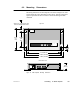
V At any node device connector, measure the resistance between pins
2 and 3 (the signal pins). The resistance should be in the range
60 ... 80 W, which includes the cable wire resistance.