
Installation guide

146 Installing the Network Cable
890 USE 100 00
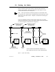
5.7 Connecting the Drop Cable
5.7.1 Connecting the Signal W ires
Detailed instructions for making the connections are enclosed in each
tap package. Below is a general description of the connections.
The drop cable contains two sets of twisted-pair signal wires with
separate shield wires. It also has an outer shield drain wire. This is a
total of seven wires.
V One set of wires is color-coded WHITE and ORANGE, with a bare
shield wire
V The other set is WHITE and BLUE, with a bare shield wire
Before connecting the wires, make sure you have identified the two sets
of twisted-pair wires. The two white wires are not interchangeable.
When you connect the wires, you must connect each wire to its proper
terminal.
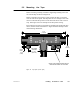
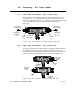
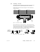
Insert the cable into the tap and secure it with a cable tie. Viewing the
tap as shown in Figure 57, connect the wires. The terminals are
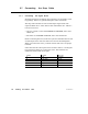
marked as follows, from left to right:
Terminal Location W ire Color
O Left ORANGE
W Left center WHITE
GND Center Shields (both sets of wires)
W Right Center WHITE
BLU Right BLUE