
Installation guide

Installing the Network Cable
890 USE 100 00
145
5.6.3 Connecting the W ires
Detailed instructions for making the connections are enclosed in each
tap package. Below is a general description of the connections.
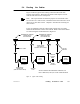
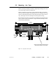
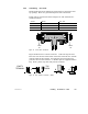
Trunk cable is connected as shown in Figure 55. The terminals are
marked as follows:
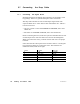
Terminal Meaning W ire Color
GND Network Bus, Ground Shield
W Network Bus, White WHITE
BLK Network Bus, Blue or Black BLUE or BLACK
CABLE
TIE
CABLE
TIE
W
GND
BLK
W
GND
BLK
Figure 55 Trunk Cable Connections
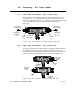
Figure 56 shows how to connect each wire. (A) Do not strip the wire.
Place the wire into the terminal slot so that the end of the wire is flush
with the inside of the terminal. (B) Using the proper insertion tool,
press the wire into the terminal. (C) Plastic caps are supplied with the
Tap. Press a plastic cap down fully into the terminal.
A B C
EMPTY
TERMINAL
TOP
VIEW
Figure 56 W ire Terminal Connection (Detail)