
Installation guide

Installing the Network Cable
890 USE 100 00
143
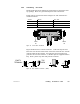
5.5 Mounting the Taps
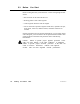
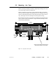
Before mounting each Tap, install the supplied grounding screw and
nut into the Tap as shown in Figure 52.
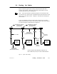
Before connecting any wiring to a Tap, mount the Tap at a location
near its node device panel. The Tap must be near enough to the node
device to allow the drop cable to reach the node device with a service
loop. See Figure 51 for an example of the drop cable routing.
The location must also be accessible for installing the trunk and drop
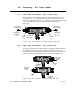
cables, and for future maintenance. Figure 52 shows the Tap’s outer
and mounting dimensions.
HOLE
DIAM.
MOUNTING
CENTERS
0.2 in
(5 mm)
3.16 in
(80.2 mm)
4.4 in
(112 mm)
2.2 in
(56 mm)
INSTALL GROUNDING SCREW AND NUT
BEFORE MOUNTING TAP ON PANEL
Figure 52 Tap Layout (Cover Open)