
Installation guide

Installing the Network Cable
890 USE 100 00
141
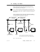
5.4 Routing the Cables
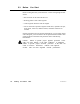
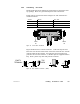
Figure 51 shows typical cable routing of the network trunk cable
between tap locations. The figure also shows cable drops to several
node devices and a service access point.
Note: The tap’s internal termination jumpers are connected at the
two end sites of a cable section, and disconnected and removed at each
inline site on the cable section. Chapter 1 describes the meaning of a
cable section.
If you are installing cables for a dual-cable network, the two cables
should be identified as Cable A and Cable B. Each of the cables should
be routed using the methods shown in Figure 51.
NODE
DEVICE
NODE
DEVICE
NODE
DEVICE
ACCESS
SERVICE
END
LOCATION LOCATION
INLINE
LOCATION
INLINE
END
LOCATION
TRUNK CABLE
SECURED IN
RACEWAY OR CONDUIT
STRAIN
RELIEFS
DROP CABLE
SERVICE
LOOP
NODE DEVICE
CONNECTOR
(PART OF DROP CABLE)
POINT
SHOWS A SINGLE-CABLE NETWORK CABLE RUN, OR
EACH CABLE RUN (A OR B) ON A DUAL-CABLE NETWORK
TERMINA
TION
JUMPERS
CONNECTED IN
EACH END TAP
TERMINA
TION
JUMPERS
REMOVED FROM
EACH INLINE TAP
Figure 51 Typical Cable Routing