
Installation guide


Documenting the Network Layout
890 USE 100 00
131
4.9 Cable Routing W orksheet
Wherever possible, obtain a site layout for your plant facility and use it
to plot your network cable routing. If no drawing is available, use the
Cable Routing Worksheet in this guide. Adapt the blank worksheet in
Appendix C as needed for your network cable path.
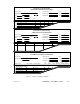
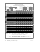
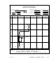
Figure 49 shows an example of a completed Cable Routing Worksheet.
The example shows a network of four nodes, plus one additional
connector for future service access. The site locations correspond to
those shown on the Network Planning Worksheet.
Note: You can use this worksheet for: (a) a single-cable network;
(b) each cable on a dual-cable network; or (c) both cables on a
dual-cable network.
Single-cable network —Show the cable routing.
Dual-cable network, each cable —Use a separate planning sheet for each
cable. Check ‘CABLE A’ or ‘CABLE B’ as appropriate in the top area of
the sheet. Show the cable routing. You can use a different grid scale
for each cable, if appropriate.
Dual-cable network, both cables— Check both ‘CABLE A’ and ‘CABLE
B’ in the top area of the sheet. Show the cable routing for both cables.
Make sure to mark the sheet so that each cable (A or B) is properly
identified over its entire run.
Top of W orksheet
If applicable, identify the plant facility or area, network, and project.
Show how to contact the responsible project engineer and maintenance
person.
You can enter grid scale dimensions at the top of the worksheet to plot
your cable routing. You can use separate dimensions horizontally
(grids A ... F) and vertically (grids 1 ... 5). For example, each grid can
represent a square site area such as 10 m X 10 m, or a rectangular area
such as 10 m X 50 m. If you wish, you can leave the scale blank and
mark each cable run length directly onto the worksheet.
You can also make multiple copies of this worksheet, and use a
relatively small scale on some sheets to show local placement of devices