
Installation guide
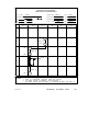


Documenting the Network Layout
890 USE 100 00
129
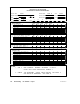
Trunk Cable and Taps
Estimate the length of the cable between sites. Each segment except
the first has a cable run from the previous site (line 2A). A service loop
in included (line 2B) to eliminate pulling or twisting of the cable.
Include all vertical routing (such as runs between floor levels), and all
horizontal routing (such as bends around ventilating shafts). Add
these lengths and enter their total into line 2C. Multiply this times 1.1
(providing an additional 10 percent) for finished dressing of the cable,
and enter this final length into line 2D. This is the cut length for each
segment.
Make sure that the minimum length that will result between any pair
of nodes will be 10 ft (3 m) or more. Make sure that the combined
lengths between all nodes on a cable section will be 1500 ft (450 m) or
less.
Enter an ‘X’ into line 2E for each site, showing that a tap is to installed.
At the two end sites on the network section, enter an ‘X’ into line 2F to
show that the tap’s termination jumpers are to be installed.
Drop Cables
Enter an ‘X’ into line 3A or 3B for the drop cable at each site. Ensure
that the drop cable is long enough to allow a service loop for
maintenance.
Device Type
Specify the device to be installed at each site. For programmable
controllers, enter the model number into line 4E. For host network
adapters enter the model number (SA85, SM85, etc) into line 4F. For
other devices, enter the model number or an ‘X’ into the appropriate
line (4A through 4K) for each site. Include at least one access point
(line 4A) at a convenient site for future service.