
Installation guide


128 Documenting the Network Layout
890 USE 100 00
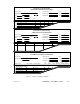
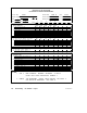
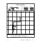
4.8 Network Planning W orksheet
Each network planning worksheet can document up to eight sites. Use
additional worksheets as required. Figure 48 is an example of a
completed Network Planning Worksheet. The example shows a
network of four nodes (two controllers, one SA85 Network Adapter, and
one BP85 Bridge Plus), plus one additional tap and drop cable for
future service access.
Note: You can use this worksheet for: (a) a single-cable network;
(b) each cable on a dual-cable network; or (c) both cables on a
dual-cable network.
Single-cable network —Enter the complete information in all areas of
the sheet.
Dual-cable network, each cable —Use a separate planning sheet for each
cable. Check ‘CABLE A’ or ‘CABLE B’ as appropriate in the top area of
the sheet. Enter the Site Labeling and Cable Length information for
the cable. In the Device Type area, you should enter the network
device types (except for RR85 Repeaters) only once, on the ‘CABLE A’
sheet. You should enter the RR85 Repeaters on both sheets (RR85
Repeaters are used on both cables).
Dual-cable network, both cables —Check both ‘CABLE A’ and ‘CABLE
B’ in the top area of the sheet. In the Site Labeling area, use a labeling
method that will properly identify each cable. In the Cable Length
area, make sure to enter the total length for both cables, including the
service loops on both cables.
Top of W orksheet
If applicable, identify the plant facility or area, network, and project.
Show how to contact the responsible project engineer and maintenance
person.
Site Labeling
Provide a labeling method for identifying network components. Enter
site names into line 1A, such as department names or floor/room
numbers. If a grid locator system is used, enter site coordinates into
line 1B. If a device enclosure or cabinet is used, identify it in line 1C.
Enter further information into lines 1D through 1G to identify each
site’s mounting panel, device, and incoming/outgoing cable runs.