
Installation guide


122 Documenting the Network Layout
890 USE 100 00
4.4 Topology Planning W orksheet
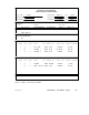
Figure 46 is an example of a completed Topology Planning Worksheet.
The example shows two networks that are interconnected by a BP85
Bridge Plus. Each device’s network node address, type, application,
and site location are listed.
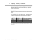
Top of W orksheet
If applicable, identify the plant facility or area, network, and project.
Show how to contact the responsible project engineer and maintenance
person.
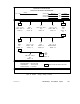
Network Topology Area
Lay each network out in a linear path for clarity. Use an END symbol
to show the two physical ends of each network section. Make four
entries to identify each node device. Use the following legend:
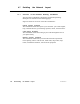
Entry Number Entry Content Meaning
First Node number The device’s address on the network
Second Device type The device’s model number
Third Application The title of the device’s application or use
Fourth Location The device’s site location in your facility
Use additional entries as needed to further identify each node in your
application.