
Installation guide


Estimating Network Performance
890 USE 100 00
113
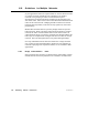
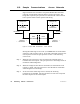
Step 4 When the peer processor in unit B acquires the token, it sends the
data response to the bridge. The peer processor in the bridge sends an
immediate acknowledgement.
Step 5 When the bridge has the token on network A, it transmits
thedataresponse to unitA. The peer processor in unit A sends an
immediate acknowledgement.
Step 6 At the end of the ladder logic scan in unit A, the incoming
transactions are handled. The transaction is complete at the next
solve time of the MSTR function in unit A. Data registers will be
written, and the MSTR function’s COMPLETE output goes ON.
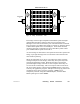
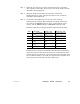
The time required to process the complete communication would be:
Event Time Range A verage T ime W orst Case Time
1 0 ... 1 token rotation,
net A
1/2 token rotation,
net A
1 token rotation, net
A
2 0 ... 1 token rotation,
net B
1/2 token rotation,
net B
1 token rotation, net
B
3 0 ... 1 scan, unit B 1/2 scan, unit B 1 scan, unit B
4 0 ... 1 token rotation,
net B
1/2 token rotation,
net B
1 token rotation, net
B
5 0 ... 1 token rotation,
net A
1/2 token rotation,
net A
1 token rotation, net
A
6 0 ... 2 scans, unit A 1 scan, unit A 2 scans, unit A
If the scan time in unit B is much shorter than the token rotation time,
unit B can create the data response and have it ready before the token
reaches unit B’s peer processor. On the other hand, if a data path is not
free in either the bridge or in unit B, the request will be queued by that
unit’s peer processor and will wait until a path is free.