
Installation guide


Estimating Network Performance
890 USE 100 00
109
NETWORK
A
NETWORK
B
DS
DM
DM
DS
DS
DS
DS
DS
DS
DS
DS
DM
DM
DM
DM
DM
DM
DM
DM
DM
DM
DM
DM
DM
DM
DS
DS
DS
DS
DS
DS
DS
BP85 BRIDGE PLUS
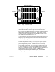
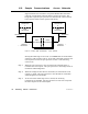
Figure 42 Bridge Communication Paths
The bridge contains eight independent Data Master paths and eight
independent Data Slave paths for each of its two network ports.
Messages received at the network A port with destinations on network
B or beyond are given Data Slave paths on network A, and then passed
to Data Master paths at the network B port. In the other direction,
incoming messages at network B are given Data Slave paths at that
port and Data Master paths at network A.
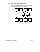
As each message is allocated one slave path and one master path in the
bridge, up to eight messages can be routed from each network to the
other without queueing.
When all eight paths are in use in a given direction, other incoming
messages will queue in the bridge, unless they have previously been
routed through another bridge. Messages that have already been
passed through a bridge will cause an error response when they are
received at the second bridge. The error response will be returned to
the error status register of the originating MSTR function, and can be
tested by the application program. This prevents tieing up paths in the
originating device due to excessive queueing. MSTRs can be
temporarily released (using their ABORT inputs), and their Data
Master paths given to other MSTRs.