
Installation guide


890 USE 100 00
xiv Contents
Illustrations
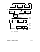
Figure 1 Network Overview 3. . . . . . . . . . . . . . . . . . . . . . . . . . . . . . . . . . . . . . . . .
Figure 2 Standard Network Terminology 4. . . . . . . . . . . . . . . . . . . . . . . . . . . . . .
Figure 3 Distributed I/O Network Terminology 5. . . . . . . . . . . . . . . . . . . . . . . .
Figure 4 Token Rotation Sequence 7. . . . . . . . . . . . . . . . . . . . . . . . . . . . . . . . . . .
Figure 5 Cable Tap Layout 9. . . . . . . . . . . . . . . . . . . . . . . . . . . . . . . . . . . . . . . . . .
Figure 6 Section Physical Layout (Single Cable) 9. . . . . . . . . . . . . . . . . . . . . . .
Figure 7 Section Physical Layout (Dual Cables) 9. . . . . . . . . . . . . . . . . . . . . . . .
Figure 8 Network Option Module 11. . . . . . . . . . . . . . . . . . . . . . . . . . . . . . . . . . . .
Figure 9 DIO Drop Adapter 12. . . . . . . . . . . . . . . . . . . . . . . . . . . . . . . . . . . . . . . . . .
Figure 10 TIO Module 13. . . . . . . . . . . . . . . . . . . . . . . . . . . . . . . . . . . . . . . . . . . . . .
Figure 11 Example of the SA85 and Host Configuration 14. . . . . . . . . . . . . . . .
Figure 12 Hierarchical Configuration for Improved Throughput 22. . . . . . . . .
Figure 13 Network for Deterministic I/O Timing 23. . . . . . . . . . . . . . . . . . . . . . .
Figure 14 Peer Cop Example 26. . . . . . . . . . . . . . . . . . . . . . . . . . . . . . . . . . . . . . . . .
Figure 15 Basic Configuration Example 28. . . . . . . . . . . . . . . . . . . . . . . . . . . . . . .
Figure 16 Maximum Linear Configuration of a Single Network 29. . . . . . . . .
Figure 17 Placing Repeaters on Dual-cable Networks 30. . . . . . . . . . . . . . . . . .
Figure 18 NonLinear Expansion 31. . . . . . . . . . . . . . . . . . . . . . . . . . . . . . . . . . . .
Figure 19 Message Routing Through Multiple Networks 32. . . . . . . . . . . . . . . .
Figure 20 Message Frame Routing Path Field 33. . . . . . . . . . . . . . . . . . . . . . . . .
Figure 21 Basic Hierarchical Configuration 34. . . . . . . . . . . . . . . . . . . . . . . . . . .
Figure 22 Modbus Devices Multiplexed to Modbus Plus 36. . . . . . . . . . . . . . . .
Figure 23 Unique Device Addressing and Parameters 38. . . . . . . . . . . . . . . . . .
Figure 24 Userprogrammed BM85 Application 40. . . . . . . . . . . . . . . . . . . . . . .
Figure 25 Network Cable System Components 44. . . . . . . . . . . . . . . . . . . . . . . .
Figure 26 Dual-Cable Layout: Illegal Lengths 50. . . . . . . . . . . . . . . . . . . . . . . . .
Figure 27 Concurrent Multiple Operations 56. . . . . . . . . . . . . . . . . . . . . . . . . . . .
Figure 28 Handling Multiple Operations 58. . . . . . . . . . . . . . . . . . . . . . . . . . . . . .
Figure 29 BP85 Bridge Plus Queueing 62. . . . . . . . . . . . . . . . . . . . . . . . . . . . . . . .
Figure 30 MSTR Function Format 64. . . . . . . . . . . . . . . . . . . . . . . . . . . . . . . . . . . .