
Installation guide


100 Estimating Network Performance
890 USE 100 00
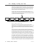
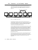
3.20 Precautions for Hot Standby Layouts
A case exists in which a node can leave the network and rejoin it
without the control of the user application. This can occur when two
nodes are connected in a hot standby configuration, as shown in
Figure 41.
MODBUS PLUS NETWORK
CPU
1 2 3 4 36 5
CPU CPU
CPU A CPU B
CPU
HOT STANDBY CONFIGURATION
PRIMARY SECONDARY
Figure 41 Hot Standby Ring Join Time
Programmable Controllers connected in hot standby each have a
network address. Both nodes are active, with the two addresses offset
by 32, as shown in Figure 41. As long as no transfer occurs between
the primary and secondary controllers, the token is passed in the
network’s usual ascending address sequence.
If a hot standby transfer occurs, CPU B assumes the primary role and
CPU A becomes the secondary. To maintain consistency in application
programming among the nodes, CPUs A and B must also exchange
node addresses. For this to occur, both nodes must momentarily leave
the network and then rejoin it after the transfer has taken place.
At that point CPU B (the new primary) then continues as node address
4, handling its traffic with the other nodes in the manner that you
programmed for node 4.
Both nodes must be separately invited to rejoin through the ring-join
process outlined on the previous page. This requires the use of an
internal message counter and next-try address that are maintained by
the network nodes and which are beyond the control of the user
application.