Modicon Modbus Plus Network Planning and Installation Guide 890 USE 100 00 Version 3.0 April 1996 AEG Schneider Automation, Inc.
Preface The data and illustrations found in this book are not binding. We reserve the right to modify our products in line with our policy of continuous product development. The information in this document is subject to change without notice and should not be construed as a commitment by AEG Schneider Automation, Inc. AEG Schneider Automation assumes no responsibility for any errors that may appear in this document.
Contents Chapter 1 Introducing the Modbus Plus Network ....................... 1 Introducing the Modbus Plus Network . . . . . . . . . . . . . . . . . . . . . . . . . . . 1.1.1 Modbus Plus Applications . . . . . . . . . . . . . . . . . . . . . . . . . . . . 1.1.2 Extending the Network . . . . . . . . . . . . . . . . . . . . . . . . . . . . . . 1.1.3 Bridging Networks . . . . . . . . . . . . . . . . . . . . . . . . . . . . . . . . . . 1.1.4 Network Example . . . . . . . . . . . . . . . . . . . . . . . .
Chapter 1 Introducing the Modbus Plus Network (Continued): 1.11 Expanding the Network . . . . . . . . . . . . . . . . . . . . . . . . . . . . . . . . . . . . . . . . . 1.11.1 Linear Expansion . . . . . . . . . . . . . . . . . . . . . . . . . . . . . . . . . . . 1.11.2 Using RR85 Repeaters . . . . . . . . . . . . . . . . . . . . . . . . . . . . . . . 1.11.3 Expanding Dual-cable Networks . . . . . . . . . . . . . . . . . . . . . . 1.11.4 Non Linear Expansion . . . . . . . . . . . . . . . . . . . . . . . .
Chapter 2 Elements of Network 2.1 2.2 2.3 890 USE 100 00 Planning ............................... 41 An Overview of Network Planning . . . . . . . . . . . . . . . . . . . . . . . . . . . . . . . 2.1.1 Preparing a Network Plan . . . . . . . . . . . . . . . . . . . . . . . . . . . Defining the Network Components . . . . . . . . . . . . . . . . . . . . . . . . . . . . . . . 2.2.1 Modbus Plus Trunk Cable . . . . . . . . . . . . . . . . . . . . . . . . . . . . 2.2.2 Modbus Plus Drop Cables . . . . . . . .
Chapter 3 Estimating 3.1 3.2 3.3 3.4 3.5 3.6 3.7 3.8 3.9 3.10 3.11 3.12 3.13 3.14 3.15 viii Contents Network Performance ............................ 51 Overview . . . . . . . . . . . . . . . . . . . . . . . . . . . . . . . . . . . . . . . . . . . . . . . . . . . . . . 3.1.1 Your Network Performance Goal and Options . . . . . . . . . . 3.1.2 Design Options for I/O Servicing . . . . . . . . . . . . . . . . . . . . . . Factors for Planning . . . . . . . . . . . . . . . . . . . . . . . . . . . . .
3.16 Predicting Node Dropout Latency Time . . . . . . . . . . . . . . . . . . . . . . . . . . . 3.16.1 How the Network Handles Node Dropouts . . . . . . . . . . . . . 3.16.2 The Latency Formula . . . . . . . . . . . . . . . . . . . . . . . . . . . . . . . . 3.17 Estimating Latency for a Small Network . . . . . . . . . . . . . . . . . . . . . . . . . 3.18 Estimating Latency for a Large Network . . . . . . . . . . . . . . . . . . . . . . . . . 3.19 Planning for Ring Join Time . . . . . . . . . . . . . . . . .
Chapter 4 Documenting the Network Layout ........................... 111 Documenting Your Network Layout . . . . . . . . . . . . . . . . . . . . . . . . . . . . . . Worksheets for Network Planning . . . . . . . . . . . . . . . . . . . . . . . . . . . . . . . . Defining Your Node Requirements . . . . . . . . . . . . . . . . . . . . . . . . . . . . . . . Topology Planning Worksheet . . . . . . . . . . . . . . . . . . . . . . . . . . . . . . . . . . . Estimating Cable Lengths . . . . . . . . . . . . . . .
Chapter 6 Connecting 6.1 6.2 6.3 6.4 6.5 an RR85 Repeater . . . . . . . . . . . . . . . . . . . . . . . . . . . . . . . 147 Mounting Methods . . . . . . . . . . . . . . . . . . . . . . . . . . . . . . . . . . . . . . . . . . . . . 6.1.1 Horizontal Mounting . . . . . . . . . . . . . . . . . . . . . . . . . . . . . . . . 6.1.2 Vertical Mounting . . . . . . . . . . . . . . . . . . . . . . . . . . . . . . . . . . . Mounting Dimensions . . . . . . . . . . . . . . . . . . . . . . . . . . . . . . . . . . . .
Appendix A Modbus Plus Transaction A .1 A .2 Transaction T iming Elements A .1.3 Data R esponse The Message Format HDLC The Message The Message Format The Modbus Modbus B .3 Controller B .4 Bridge Format 174 ............................... 176 ........................................ L evel 176 ................................ 178 ......................................... 178 LLC L evel ................................. 180 .......................................... 181 . . .
Appendix Installing D Custom . . . . . . . . . . . . . . . . . . . . . . . . . . . . 207 D .1 Overview D .2 Tools and Test Equipment D .3 Before D .4 R outing the Cable D .5 Installing Connectors on Dual-Cable R uns . . . . . . . . . . . . . . . . . . . . . . . . . . . 213 D .6 Installing Connectors W ith the Tool . . . . . . . . . . . . . . . . . . . . . . . . . . . . . . . . . 214 D .7 208 ................................ 209 ................................................
Illustrations xiv Figure 1 Figure 2 Figure 3 Figure 4 Figure 5 Network Overview . . . . . . . . . . . . . . . . . . . . . . . . . . . . . . . . . . . . . . . . . Standard Network Terminology . . . . . . . . . . . . . . . . . . . . . . . . . . . . . . Distributed I/O Network Terminology . . . . . . . . . . . . . . . . . . . . . . . . Token Rotation Sequence . . . . . . . . . . . . . . . . . . . . . . . . . . . . . . . . . . . Cable Tap Layout . . . . . . . . . . . . . . . . . . . . . . . . . . . . . . . .
890 USE 100 00 Figure 31 Figure 32 Figure 33 Figure 34 Figure 35 Sample READ Communication . . . . . . . . . . . . . . . . . . . . . . . . . . . . . Sample GET LOCAL STATISTICS . . . . . . . . . . . . . . . . . . . . . . . . . . Sample GET REMOTE STATISTICS . . . . . . . . . . . . . . . . . . . . . . . . Sample Global Database Pass . . . . . . . . . . . . . . . . . . . . . . . . . . . . . . Token Rotation Time . . . . . . . . . . . . . . . . . . . . . . . . . . . . . . . . . . . . . .
xvi Figure 61 Figure 62 Figure 63 Figure 64 Figure 65 RR85 Repeater Rear Panel View . . . . . . . . . . . . . . . . . . . . . . . . . . . . RR85 Repeater Indicators . . . . . . . . . . . . . . . . . . . . . . . . . . . . . . . . . . BP85 Bridge Plus Dimensions (Panel/Shelf Models) . . . . . . . . . . BP85 Bridge Plus Dimensions (Rack Mount Model) . . . . . . . . . . . BP85 Network Address Switch Settings . . . . . . . . . . . . . . . . . . . . .
890 USE 100 00 Figure 91 Figure 92 Figure 93 Figure 94 Figure 95 Preparing the Cable . . . . . . . . . . . . . . . . . . . . . . . . . . . . . . . . . . . . . . . Placing the Connector into the Tool . . . . . . . . . . . . . . . . . . . . . . . . . Determining the Wiring Direction . . . . . . . . . . . . . . . . . . . . . . . . . . Replacing the Cap . . . . . . . . . . . . . . . . . . . . . . . . . . . . . . . . . . . . . . . . . Seating the Wires and Installing the Cap Screw . . . . . . . . . . . . . .
Related Publications Refer to the following publications for further information about the Modbus Plus network and other Modicon products.
Chapter 1 Introducing Network the Modbus Plus V Introducing the Modbus Plus Network V Network Terminology V Overview of the Logical Network V Overview of the Physical Network V Major Components of the Network V How Nodes Access the Network V Error Checking and Recovery V Designing for Process Speed V Designing for Deterministic I/O Servicing V Using Peer Cop V Expanding the Network V Joining Modbus Plus Networks V Bridging Modbus Plus and Serial Devices 890 USE 100 00 Introducing the Modbus Plus Netw
1.1 1.1.1 Introducing Modbus the Modbus Plus Network Plus Applications Modbus Plus is a local area network system for industrial control applications. Networked devices can exchange messages for the control and monitoring of processes at remote locations in the industrial plant. Modicon products supporting Modbus Plus communication include programmable controllers and network adapters. The network is also supported by a variety of products from other manufacturers.
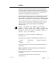
Modbus Plus networked devices, as well as with other devices at the serial ports. 1.1.4 Network Example Figure 1 shows four Modbus Plus networks. A Repeater extends the cable for Network A. Networks A and B are joined by a Bridge Plus. Networks C and D handle I/O processes. DIO Drop Adapters and Terminal Block I/O modules service the I/O field devices at each site.
CPU RR85 REPEATER CPU UP TO 64 NODES TOTAL NETWORK A BP85 BRIDGE PLUS HOST DEVICE NETWORK ADAPTER BM85 BRIDGE MULTIPLEXER MODBUS OR CUSTOM SERIAL DEVICES USER INTERFACE HOST COMPUTER NETWORK B P S C P U N O M N O M D I O I/O MODULES UP TO 64 NODES TOTAL I/O MODULES TIO NETWORK C D I O NETWORK D Figure 4 Introducing 1 N etwork the Modbus UP TO 64 NODES TOTAL I/O MODULES TIO TIO UP TO 64 NODES TOTAL Overview Plus Network 890 USE 100 00
1.2 Network Terminology The following terms are used in this guide to describe network elements: Network The grouping of nodes on a common signal path that is accessed by the passing of a token. It consists of one or more cable sections. For example, all of the nodes in Figure 2 are on a network .
Node Any device that is physically connected to the Modbus Plus cable. Figure 2 shows a network with seven node devices. The term applies to any device, whether it is addressable or not. Some nodes , like programmable controllers, have addresses and can serve as sources or destinations for messages. The Bridge Plus is a separately addressable node on each of its two networks. The Repeater is a node on each of two sections, but has no address, serving only to extend the network.
1.3 Overview of the Logical Network Network nodes are identified by addresses assigned by the user. Each node’s address is independent of its physical site location. Addresses are within the range of 1 to 64 decimal, and do not have to be sequential. Duplicate addresses are not allowed. Network nodes function as peer members of a logical ring, gaining access to the network upon receipt of a token frame.
Figure 4 shows the token sequences in two networks joined by a Bridge Plus. NETWORK 1 TOKEN SEQUENCE: 2 5 2 10 12 22 2... 12 NODE 10 22 NODE NODE 5 NODE BRIDGE PLUS 24 5 10 NODE 4 NODE NODE TOKEN SEQUENCE: 4 5 NETWORK 2 Figure 8 Introducing 4 Token Rotation the Modbus 9 10 24 9 NODE 4...
1.4 Overview of the Physical Network The network bus consists of twisted-pair shielded cable that is run in a direct path between successive nodes. The two data lines in the cable are not sensitive to polarity, however a standard wiring convention is followed in this guide to facilitate maintenance. The network consists of one or more cable sections, with any section supporting up to 32 nodes at a maximum cable distance of 1500 ft (450 m).
NETWORK TRUNK CABLE NETWORK TRUNK CABLE CABLE TIE TAP SHOWN WITH COVER OPEN TERMINATION JUMPERS (2) END SITES: CONNECTED TO PINS AT OPPOSITE SIDE FROM TRUNK CABLE ENTRY INLINE SITES: OPEN Figure 5 GROUND WIRE DROP CABLE TO NODE Cable Tap Layout The next two figures summarize the layout for one section of a network. UP TO 32 NODES MAX., 1500 ft (450 M) CABLE MAX. 10 ft (3 M) CABLE MIN.
1.5 1.5.1 Major Components Programmable of the Network Controllers Modicon controllers connect directly to the network bus cable through a dedicated Modbus Plus communication port that is located on the controller assembly. The port allows the controller to communicate with other networked controllers, host computers with network adapters, and DIO drops. Controller models are available for single-cable and dual-cable network layouts.
Note: The address exchange can cause a momentary delay in communication with the new primary unit while it assumes its place in the network token rotation sequence. This can be a significant factor in the timing of processes using redundant controllers. The application should provide retry capabilities in the other nodes to cover this time. 1.5.2 Network Option Modules The Network Option Module (NOM) mounts in the backplane with the controller.
1.5.3 DIO Drop Adapters The DIO Drop Adapter mounts in a housing at a remote site, communicating over the housing backplane to the site’s I/O modules to service the site’s data requirements. The adapter includes a built-in power supply that provides operating power for the I/O modules. DIO Adapters are available for single-cable and dual-cable network layouts. Contact your Modicon distributor for information about models and part numbers. Figure 9 shows the front view of a typical DIO Drop Adapter.
1.5.4 Available Backplanes for DIO Applications Modicon backplanes are available in sizes from 2 ... 16 slots. The DIO Drop Adapter module occupies one slot, and contains a power supply that furnishes operating power to the housing for I/O modules. The supply’s capacity is 3.0 A. 1.5.5 Terminal Block I/O (TIO) Modules Remote sites can be serviced using Terminal Block (TIO) modules.
1.5.6 Network Adapters for Host Computers Adapters are available for connecting host computers to the Modbus Plus network. The SA85 Network Adapter connects an IBM AT or compatible product to the network. The SM85 Network Adapter connects an IBM Personal System/2 or compatible product using a MicroChannel bus. The SQ85 connects a DEC MicroVAX II or 3000. Figure 11 shows an example of the configuration of an SA85 adapter into an IBM AT-compatible host computer.
Typical network adapter applications include: V User interfaces V Control, monitoring, and reporting of remote processes V Program load/record/verify operations V Online programming V Bridging between Modbus Plus and other networks V Testing and debugging of application programs V Running network diagnostic programs. Modbus commands received from the Modbus Plus network that are addressed to the network adapter can be given to tasks running in the computer.
1.5.7 BM85 Bridge Multiplexer The BM85 Bridge Multiplexer provides connection to Modbus Plus for up to four kinds of serial devices. Four BM85 models are available. Two of these connect Modbus devices, or networks of Modbus devices, to the Modbus Plus network. Each of the Modbus ports can be separately configured to support a Modbus master device, slave device, or network of slave devices. Port parameters are also separately configurable.
1.5.9 RR85 Repeater The RR85 Repeater allows you to place more than 32 nodes on the network and to increase the cable distance up to an additional 1500 ft (450 m). It functions as an amplifier and signal conditioner to maintain adequate signal levels between its two sections of the network. Up to three Repeaters may be present in the message path between the source and destination nodes. You can therefore join up to four sections along a single linear path.
1.6 1.6.1 How Nodes Access How Your Application’ the Network s Layout Affects Node Access When the network is initialized, each node becomes aware of the other active nodes. Each node builds a table identifying the other nodes. Initial ownership of the token is established, and a token rotation sequence begins. Your choice between laying out your application as one large network, or as several smaller networks, affects the timing of the complete token rotation.
1.6.3 Point to Point Message Transactions While a node holds the token, it sends its application messages if it has any to transmit. Each message can contain up to 100 controller registers (16 bit words) of data. The other nodes monitor the network for incoming messages. When a node receives a message, it sends an immediate acknowledgment to the originating node. If the message is a request for data, the receiving node will begin assembling the requested data into a reply message.
Global database applications include time synchronization, rapid notification of alarm conditions, and multicasting of setpoint values and constants to all devices in a common process. This allows uniform and rapid transmission of global data without having to assemble and transmit separate messages to the individual devices. Access to a network’s global database is available only to the nodes on that network, because the token is not passed through bridge devices to other networks.
1.7 Error Checking and Recovery When a node sends a data message, it expects an immediate acknowledgment of receipt by the destination. If none is received, the node will attempt up to two retries of the message. If the final retry is unsuccessful, the node sets an error which can be sensed by the application program. If a node detects a valid transmission from another node using the same address, the node becomes silent and sets an error which can be sensed by the application.
1.8 Designing for Process Speed Figure 12 is an example of a hierarchical approach using Bridge Plus devices. The application uses a relatively large count of nodes, but no network contains more than six nodes. Token access and message handling can be rapid within the networks that are used for the control of time critical processes. For example, the node count on a given network can be reduced to the minimum that is required for that portion of the application.
1.9 Designing for Deterministic I/O Servicing Figure 13 illustrates a network designed for deterministic timing of I/O processes. The I/O network consists only of the CPU and I/O drops. A User Interface (UI) device is connected to a separate network at the NOM port.
1.10 Using Peer Cop 1.10.1 Peer Cop Transactions Point to point data can be transacted while a node holds the token and during its token pass with Modbus Plus Peer Cop. Up to 500 words (16 bits each) can be directed to specific data references in node devices prior to release of the token, and up to 32 words can be globally broadcast to all nodes as part of the token frame. Because all nodes monitor the network, each node can extract data that is specifically addressed to that node.
Receiving Data Nodes can be configured to receive two kinds of Peer Cop data: V Global Input Up to 32 words of global data can be received by each node from each other node on the network. Destination references are specified in the receiving node’s configuration. Up to eight blocks of references can be specified, giving up to eight separate destinations for the data received from each source node.
1.10.2 A Peer Cop Example Figure 14 shows a network with three nodes that are handling Peer Cop data transfers. Other nodes are also present elsewhere on the network.
has not been configured to receive Global Input from node 2, and ignores it. The node receives Specific Input and maps it to its references 10201 ... 10216. Node 7 References Ignored Node 5 is also configured to receive Specific Input from node 10, and node 7 is configured to receive Global Input from node 18. These other references are not involved in the transactions from node 2. Nodes 5 and 7 could also be configured to make output transactions when they pass the token.
1.1 1 Expanding 1.1 1.1 Linear the Network Expansion The simplest network configuration consists of two or more nodes connected to a single section. Figure 15 shows four nodes connected in a basic dual-cable configuration. UP TO 32 NODES MAX., 1500 ft (450 M) CABLE MAX. 500 ft (150 M) CABLE MAX. DIFFERENCE, CABLE A TO B MEASURED BETWEEN ANY PAIR OF NODES 10 ft (3 M) CABLE MIN.
1.1 1.2 Using RR85 Repeaters If your network requires more than 1500 ft (450 m) of cable, or more than 32 nodes, you can install RR85 Repeaters to expand the network. The repeaters must be sited so that no single section of the network exceeds the maximum length of 1500 ft (450 m) of cable, and no single section contains more than 32 nodes. Up to three repeaters can be present in the cable path between any two nodes that will communicate with each other.
1.1 1.3 Expanding Dual-cable Networks On dual-cable networks, repeaters must be placed between the same node devices, maintaining a logical symmetry to the two cable paths. Figure 17 illustrates this.
1500 ft CABLE MAX. ND ND ND ND RR ND = NODE DEVICE RR = REPEATER 1500 ft CABLE MAX. RR RR ND ND RR 1500 ft CABLE MAX. 1500 ft CABLE MAX. ND ND ND ND ND ND ND ND Figure 32 Introducing 18 the Modbus Non Linear 1500 ft CABLE MAX.
1.12 Joining Modbus 1.12.1 How the Bridge Plus Networks Plus Operates The BP85 Bridge Plus device connects as a node on each of two Modbus Plus networks. The Bridge operates as an independent node on each network, receiving and passing tokens according to each network’s address sequence. Bridge Plus devices are not applicable to networks used for Distributed I/O applications. Figure 19 shows three networks (A, B, and C) joined by a pair of Bridge Plus devices.
If a data message intended for a remote node is received at one of the Bridge’s ports, the Bridge stores the message, and then forwards it to a node address on the next network as soon as it has received the token to transmit on that network. Each message frame contains routing information that allows it to be passed through successive Bridges to a final destination node on a remote network. The routing path is specified when the message is created by the user’s application program.
When the first Bridge (22) receives the original message, it examines the routing field and determines that routing is required to its other network port (the next address in the field is not a zero). The Bridge removes its address from the routing field, shifting the remaining addresses in the field one place to the left and zero filling the field from the right. This places the next routing address (20) into position 1 of the field.
The types of devices used in your application determine how many Modbus Plus networks you can join. V You can address a programmable controller destination on a remote network that is up to four networks away from the originating node (that is, with four bridges in the message path). V Host based network adapters can be addressed up to three networks away (through three bridges). V A single Modbus slave device at a Bridge Multiplexer port can also be addressed up to three networks away.
1.13 Bridging Modbus 1.13.1 How the Bridge Plus and Serial Devices Multiplexer Operates The BM85 Bridge Multiplexer device operates as a standard Modbus Plus node, receiving and passing tokens in the network’s address sequence. It provides four serial port connections to allow Modbus Plus nodes to communicate with serial devices. BM85 models are available for support of Modbus, RS232, and RS485 serial devices. 1.13.
Modbus master devices connected to the Bridge Multiplexer can access any controller node on the Modbus Plus network, including nodes on remote networks through Bridge Plus devices. A master device can also access a slave device connected to another port on the local Bridge Multiplexer, or one connected to a remote Bridge Multiplexer node on Modbus Plus.
MODBUS PLUS NETWORK (UP TO 64 NODES) CPU BM85 BRIDGE MULTIPLEXER 1 2 3 4 CPU = MODBUS PORT ASCII, 9600 BAUD RTU, 4800 BAUD RTU, 9600 BAUD J478 MODBUS MODEM RTU, 4800 BAUD J478 MODBUS MODEM MODBUS NETWORK ADDRESSES 1 ... 247 Figure CPU 23 IBM PC OR COMPATIBLE (MASTER) Unique Device CPU (SLAVE) MODBUS NETWORK ADDRESSES 1 ...
The application can then be downloaded using a utility supplied with the development tools. The download host can be connected to Modbus Plus by a Modicon SA85 (ISA/AT bus) or SM85 (Microchannel bus) network adapter. The download image contains all of the internal operating code to be used in the BM85. It provides the protocols for the serial devices to establish communication with other devices: handshaking, protocol translation, packaging of messages, buffer space, data conversion, and error handling.
Figure 24 summarizes the layout of port devices in a typical BM85 user-programmed application. MODBUS PLUS NETWORK (UP TO 64 NODES) CPU BM85 BRIDGE MULTIPLEXER 1 2 3 4 CPU CPU = MODBUS PORT MODBUS DEVICE BARCODE READER SCALE DISPLAY Figure 24 User programmed BM85 Application As shown in the figure, a Modbus master or slave device could also be attached at a serial port if the user-defined code in the BM85 included a Modbus protocol handler.
Chapter 2 Elements of Network Planning V An Overview of Network Planning V Defining the Network Components V Defining the Network Layout 890 USE 100 00 Elements of Network Planning 43
2.1 An Overview of Network Planning You should consider the following factors in the layout of your Modbus Plus network: V You can design your control system from a wide range of controller performance features. You can choose your system layout from many variations in distributed control, local and remote input/output systems, and user interfaces.
worksheets. You can make photocopies of them for use in documenting your network.
2.1.1 Preparing a Network Plan This chapter provides a focus for planning your Modbus Plus network requirements and layout. Planning elements include: V Defining the network media components. These include the network trunk cable, taps, and drop cables. V Defining the network layout. This includes defining environmental requirements, estimating cable run and cut lengths, and providing access for future maintenance. V Defining the network device setup parameters.
V Bridge Plus You must define a network node address for each of the Bridge Plus device’s two network ports. This guidebook provides setup and installation information.
2.2 Defining the Network Components Figure 25 summarizes the components of the network cable system. TAP TRUNK CABLE GROUND CONNECTION THROUGH DROP CABLE DROP CABLE END NODE INLINE NODE INLINE NODE = INTERNAL JUMPERS CONNECTED Figure 25 Network Cable System END NODE = INTERNAL JUMPERS DISCONNECTED Components For ordering information, contact Modicon Customer Service at the following telephone numbers. Ask for Customer Service Order Entry.
2.2.1 Modbus Plus Trunk Cable Cable specified for Modbus Plus trunk use is available from Modicon as the following part numbers: Length of Cable on Reel Part Number 100 ft (30.5 m) 490NAA27101 500 ft (152.5 m) 490NAA27102 1000 ft (305 m) 490NAA27103 1500 ft (457 m) 490NAA27104 5000 ft (1525 m) 490NAA27106 Your cable will run directly between the network device locations. Each cable segment must be a continuous run between the taps at two locations.
2.2.3 Modbus Plus Tap A tap is required at each site on the trunk cable to provide connections for the trunk cable and drop cable. Its Modicon part number is 990NAD23000. You should plan to order a sufficient quantity of taps and drop cables to allow extra ones for service access and spares. 2.2.4 Modbus Plus Cable Impedance Termination Each tap contains an internal terminating resistor that can be connected by two jumpers. Two jumper wires are included in the tap package, but are not installed.
2.2.5 Modbus Plus Network Grounding Each tap has a grounding screw for connection to the site panel ground. Modicon drop cables have a grounding lug in the cable package. This must be installed on the cable and connected to the grounding screw on the tap. The node device end of the drop cable has a lug which must be connected to the node device’s panel ground. The network cable must be grounded through this connection at each node site, even when the node device is not present.
2.3 Defining the Network 2.3.1 Component Locations Layout The maximum cable length allowed for the network section from end to end is 1500 ft (450 m). Up to 32 nodes can be connected within this length. The maximum length includes the total set of cable runs, including all horizontal runs and vertical cable drops to the networked devices. On dual-cable networks, the difference in length between cables A and B must not exceed 500 ft (150 m) between any two nodes on the same cable section.
V In addition to the minimum separation, if the cable must cross power wiring carrying over 480 volts, it must cross only at a right angle. The cable must not run parallel to the power wiring. 2.3.3 Adding Service Connectors In addition to the drop cables to the network node devices required for your application, you should provide one or more drops to allow for service access to the active network.
V Between nodes 2 ... 4, the difference between cables A and B is also 600 ft (180 m). This exceeds the maximum allowable difference of 500 ft (150 m). NOT TO SCALE 900 ft (270 M) 150 ft (45 M) 150 ft (45 M) 450 ft (135 M) 450 ft (135 M) CABLE A CABLE B 300 ft (90 M) NODE 1 NODE 2 Figure 26 Dual-Cable NODE 3 Layout: Illegal NODE 4 Lengths Note that the cable A-to-B difference only applies to node connections on the same cable section.
Chapter 3 Estimating Network Performance V V V V Overview Factors for Planning How Devices Interact on the Network Factors That Affect Performance V V V V Communication Paths and Queueing Reading and Writing with the MSTR A Sample MSTR Communication Getting and Clearing Statistics V V V V Reading and Writing Global Data Loading Effects in Your Application Predicting Token Rotation Time Formula for Calculating Token Rotation V V V V Predicting MSTR Response Time Estimating Throughput (With MSTR) Estim
V A Summary of Network Planning 56 Estimating Network Performance 890 USE 100 00
3.1 Overview This chapter describes the major factors you should consider as you plan the layout of your Modbus Plus network. It explains how you can use MSTR and Peer Cop methods for communicating in your application, and shows how your use of these methods affects network performance. It gives examples of message handling between nodes, and presents guidelines for predicting the performance of single and multiple networks. 3.1.
Your Options You can plan your network application as a single network, with a linear arrangement of nodes. You can also plan it as multiple networks that are joined in a layered or hierarchical configuration. The choices you make will be determined by your data requirements between the nodes.
3.2 Factors for Planning When you plan an industrial communications strategy that will integrate various control systems and computer products, you’ll need to consider the kinds of applications you will implement, their information requirements, and their control devices. Your planning should be at three levels: (1) Network Applications; (2) Information Requirements; and (3) Transaction Requirements. Factors to consider are listed below. 3.2.
3.2.3 Transaction Requirements Consider the types and quantities of message transactions that must occur between networked devices.
3.3 How Devices Interact on the Network Multiple data transfer and programming operations can occur concurrently on anetwork. As an example, consider the network in Figure 27. This example shows five nodes on a single network. In practice, the network could contain up to its full complement of 64 nodes, and additional networks could be connected through Bridge Plus devices.
V Computer B in a programming or load/record/verify operation with controller 3 V Plant personnel accessing any node from the P230 programming panels using the controllers’ built-in Modbus to Modbus Plus bridge mode.
3.4 Factors 3.4.1 Handling That Affect Performance Multiple Operations The time that is required for a node to respond to a request for data is affected by the count of nodes on the network, by the number of active transactions in each node, and by each node’s instruction handling capability (scan time). The way in which you program your application also will affect the response time.
Two additional operations are occurring on the network. Computer B is in a programming or load/record/verify operation with controller 3. Plant personnel accessing any node from the P230 programming panels using the controllers’ built-in Modbus to Modbus Plus bridge mode. These operations are handling data that is not currently used in the application. Their activity on the network will, however, affect the response times for the first two operations.
written by the incoming data, and cleared by a subsequent scan), or by using transaction counters or other similar methods.
3.5 Communication Paths and Queueing With multiple devices processing messages asynchronously on the network, it becomes possible for an individual device to have several concurrent transactions in process. The peer processor in each device maintains multiple communication paths of various types. It opens a path when a transaction begins, keeps it open during the transaction, and closes it when the transaction terminates. When the path is closed, it becomes available to another transaction.
3.5.2 Path Quantities The following paths are available in the various types of Modbus Plus devices: CPU BM85 BP85 SA85/SM85 Data Master 5 4 8 8 Data Slave 4 4 8 8 Program Master 1 4 8 8 Program Slave 1 4 8 8 Data Master Paths in Controllers Five Data Master paths are provided in controllers. Of these, one path is reserved for use by the controller’s Modbus port in the bridge mode between Modbus and Modbus Plus.
BP85 Bridge Plus Queueing Messages which must pass through multiple bridges will be queued (if necessary) within the first bridge, but will not be queued within any subsequent bridges in the transaction path. Figure 29 shows an example.
Transactions are handled in this way to prevent excessive delays between requests and responses in your application. This situation should occur rarely, and is caused by high message loading within the bridge.
3.6 Reading and W riting with the MSTR The MSTR instruction is a ladder logic function that provides access to the Modbus Plus network. Its format is shown in Figure 30.
For example, in a data Read or Write operation, the Control Block layout is as follows: Register Content 4x Operation Type 4x + 1 Storage for Returned Error Status Code (if an error occurs) 1 = Write 2 = Read x +2 Data Block Length 4 4x + 3 Start of the Data Area in the Destination Device 4x + 4 Modbus Plus Routing Path 1 4x + 5 Modbus Plus Routing Path 2 4x + 6 Modbus Plus Routing Path 3 4x + 7 Modbus Plus Routing Path 4 4x + 8 Modbus Plus Routing Path 5 The Control Block register at
3.7 A Sample MSTR Communication Every Modbus Plus device has a peer processor that controls network communication. Collectively the peer processors in all of the networked devices establish and maintain the token rotation, the transmission and receipt of messages, and acknowledgements. In a programmable controller, the peer processor transfers message data to and from the MSTR functions in your ladder logic. Figure 31 shows two controllers on a Modbus Plus network.
Step 4 At the end of the ladder logic scan in unit A, the incoming transactions are handled. The transaction is complete at the next solve time of the MSTR function in unit A. Data registers will be written, and the MSTR function’s COMPLETE output goes ON. The time required to process the complete communication would be: Event T ime Range A verage 1 0 ... 1 token rotation 1/2 token rotation T ime W orst Case T ime 1 token rotation 2 0 ... 1 scan, unit B 1/2 scan, unit B 1 scan, unit B 3 0 ...
3.8 3.8.1 Getting and Clearing Local Device Statistics Statistics When you issue commands to Get Local Statistics or Clear Local Statistics, the action is handled by the local device’s peer processor. No transaction occurs on the Modbus Plus network. The operation is completed by the end of the MSTR function execution in the local device. Figure 32 illustrates a Get Local Statistics operation in controller A.
The time required to process the complete communication would be: 890 USE 100 00 W orst Case T ime T ime Range A verage 0 ... 1 token rotation 1/2 token rotation T ime 1 token rotation 0 ...
3.9 3.9.1 Reading Passing and W riting Global Global Data Between Data Nodes Up to 32 registers of global data can be included in the network token frame as it is passed between nodes. In the node currently holding the token, an MSTR function can be programmed to include global data in the next token pass. The global data will be read into the peer processors of the other nodes on the same network, and will update the storage area in those nodes.
Step 1 When the peer processor in unit A acquires the network token, it transmits any other application messages it has pending, and then passes the token. Every other node on the network reads the global data contained in the token frame and places a copy of it in its peer processor. Step 2 each other controller on the same network, an MSTR function programmed to Read Global Database can read the new global data.
3.10 Loading Effects in Your Application During the application, each node on the network can have a different number of paths constantly being opened, held active, and closing. This is a dynamic process that is affected by the count of nodes and the amount of message traffic between them. If some nodes have most of their paths active at any given moment, and others do not, the nodes with the heavy path loading will hold the token longer as they process data.
During dequeueing at the destination, the receiving node will request the command again from the originating node when the receiving node acquires the network token. The command is reissued and received while the receiving node holds the token. This process eliminates the need for continual polling, reducing the overhead in your application and the loading that would be caused by polling on the network. It does, however, tend to add some loading and to decrease the overall message throughput.
3.1 1 Predicting Token Rotation T ime Figure 35 shows a graph of token timing as a function of the network node count and message loading. The graph was constructed with a network containing Modicon programmable controllers. Message loading ranges from zero (the token pass only) to maximum loading (each controller has all four MSTR Data Master paths on, with each path passing 100 registers, and with global data passing 32 registers).
The token rotation times shown in the figure are for data transactions, with no queueing at the destination nodes and with no remote programming concurrently in progress. Rotation times can be expected to be longer if some nodes must hold the token for a longer time to process queued transactions or remote programming. Token rotation time will be slightly reduced when less than 100 registers of data are moved in each path, however this improvement will be marginal for most applications.
3.12 Formula for Calculating Token Rotation The formula for calculating the average token rotation time is: TR = (2.08 + 0.016 * DMW ) * DMP + (0.19 + 0.016 * GDW ) * GDN + 0.
For example.consider twocases in which an MSTR is enabled every scan, and the scan time is 20 ms. V Faster token If the token rotation time is estimated at 10 ms, count the Data Master path use as 0.5 path. The ratio (10/20) shows the use is one half path. V Faster scan If the token rotation time is estimated at 50 ms, count the Data Master path use as 1.0 path. Even though the ratio (50/20) is greater than unity, the use will never be more than one path.
3.13 Predicting MSTR Response T ime When you have calculated the average token rotation time on the network, you can predict the average time for a response to an MSTR data request. The response time will not include factors such as queueing or error conditions on the network. The time will be based on a request response transaction on a single network.
CPU CPU 1 CPU 2 CPU 3 CPU 4 CPU 5 6 MODBUS PLUS NETWORK Figure 36 Predicting Planning Response T ime Loading Originating Node Type of Communication 1 MSTR always ON 50 registers 2 MSTR ON for 500 ms 100 registers 3 MSTR always ON 75 registers 4 MSTR always ON 100 registers 1 MSTR always ON 75 registers 4 Global Data ON 16 registers All MSTR always ON 75 registers 4 Global Data ON 32 registers All 2 3 4 Receiving Node Guidelines are provided on the next page
The following steps can be used to calculate the data response time for an MSTR, and the acquisition time for global data. 1. Find the average token rotation time Apply the formula from Section 3.12: = (2.08 + 0.016 * DMW ) * DMP + (0.19 + 0.016 * GDW ) * GDN + 0.53 * N TR DMW = (50 + 100 + 75 + 100 + 75 + 75) / 6 = 79 words DMP = (1 + 20/500 + 1 + 1 + 1 + 1) = 5.04 paths GDW = (16 + 32) / 2 = 24 words GDN = (1 + 1) = 2 nodes N = 6 nodes TR = (2.08 + 0.016*79) * 5.04 + (0.19 + 0.
3. Calculate the global data acquisition time Each unit’s time to receive data from another unit’s Global Data Write would be: Average time Worst case time 890 USE 100 00 1/2 token rotation time 10.59 ms 1/2 scan time of the receiving unit 10 ms Total 20.59 ms 1 token rotation time 21.18 ms 1 scan time of the receiving unit 20 ms Total 41.
3.14 Estimating Throughput (W ith MSTR) Figure 37 shows a graph of the throughput per node as a function of the node count. The data rate is the quantity of registers that can be transferred per second of time. The graph was constructed with a network containing Modicon programmable controllers, with each controller’s message loading at maximum (each controller has all four MSTR Data Master paths on, with each path passing 100 registers).
Note that the network’s capacity is 20,000 registers/s. The throughput for any node is 20,000 registers/s divided by the count of nodes on the network. 3.14.1 Grouping Nodes Logically for Increased Throughput Each node’s throughput is a factor of the network’s node count and network loading, as shown in Figure 37. Consider how your node devices must communicate to the other nodes.
3.15 Estimating 3.15.1 Estimating Throughput Total Communication (W ith Peer Cop) Time With Peer Cop communication, data can be sent to specific nodes during token passes. Nodes using Peer Cop can transmit Specific Output data to one or more destinations. The destination nodes can be set to receive Specific Input data from selected sources.
The sending node A transmits its Specific Output data, containing Peer Cop data to receiving node B. Node B receives this traffic immediately as Specific Input data, and acts upon it during its next scan. The token now passes through the intervening nodes before it is passed to node B. Node B retains the token while it handles any ‘non Peer Cop’ traffic. Before node B releases the token to the next node in the address sequence, it sends the Peer Cop response data (as Specific Output) for node A.
3.16 Predicting Node Dropout 3.16.1 How the Network Handles Latency T ime Node Dropouts All active nodes maintain a member node table that identifies other nodes in the ring. When a node holds the token and completes its message traffic, it passes the token. The token is always passed to the next active node in an ascending address sequence. If the next node has left the network since its last token pass, a network timeout occurs during the attempt to pass the token.
Addresses below the drop-out This general formula is used to calculate the NDOL for each node with an address lower than that of the lowest drop-out node. This time is abbreviated NDOL(L), where (L) is the address of any remaining node. NDOL(L) = 80 + 4(lowest node address) + (qty of nodes remaining + 5(quantity of nodes dropped 1) Addresses 1) above the drop-out This general formula is used to calculate the NDOL for each node with an address higher than that of the lowest drop-out node.
3.17 Estimating Latency for a Small Network Here is an example for estimating drop-out latency in a small network of programmable controller nodes. Peer Cop transfer of Specific Input and Specific Output data is used. The network is structured as follows: V 10 nodes, Programmable Controllers addressed 2 ... 11 V Node 2 has an output of 2 registers to each of the other nine nodes (a total of 2 * 9 = 18 registers) V Nodes 3 ...
Abbreviations TTT(n) Token Transmission Time (for node n) TRT Token Rotation Time NDOL(n) Node Drop Out Latency (for node n) TN(n) Response Time, Normal (for node n) TA(n) Response Time, Abnormal (for node n) Calculations TTT(n) = (Token Pass Time: .530 + Specific Output Time: .530 +.001(Qty of Nodes Communicated * Qty of Registers * 16)) TTT(2) = (.530 + .530 + .001(9 * 2 * 16)) = 1.348 ms TTT(3...11) = (.530 + .530 + .001(1 * 2 * 16)) = 1.092 ms TRT = TTT(2) + 9(TTT(3...11)) = 11.
3.18 Estimating Latency for a Large Network Here is an example for estimating drop-out latency in a large network of programmable controller nodes. Peer Cop transfer of Specific Input and Specific Output data is used. The network is structured as follows: V 32 nodes, Programmable Controllers addressed 2 ...
Abbreviations TTT(n) Token Transmission Time (for node n) TRT Token Rotation Time NDOL(n) Node Drop Out Latency (for node n) TN(n) Response Time, Normal (for node n) TA(n) Response Time, Abnormal (for node n) Calculations TTT(n) = (Token Pass Time: .530 + Specific Output Time: .530 +.001(Qty of Nodes Communicated * Qty of Registers * 16)) TTT(master) = (.530 + .530 + .001(15 * 32 * 16)) = 8.74 ms TTT(slave) = (.530 + .530 + .001(1 * 32 * 16)) = 1.57 ms TRT = 2(TTT(master)) + 30(TTT(slave)) = 64.
3.19 Planning for Ring Join T ime Nodes can be connected to the network while it is active, dynamically joining into the address sequence. A node that was previously inactive due to a power-down state can join the active ring upon its power-up. The network automatically senses the presence of the new node and begins to include it in the address sequence.
join and does not do so, approximately 2 ms must elapse before its absence can be assumed and the token passed to the next node. The worst-case event occurs when node 64 wants to join at the moment the node that currently holds the token has a message count of 1 and a next-try address of 1 also. A minimum of 64 x 64 messages must pass before node 64 can be invited to join. The average latency for this case is approximately 6 ... 7 s. Worst-case time is approximately 15 s.
3.20 Precautions for Hot Standby Layouts A case exists in which a node can leave the network and rejoin it without the control of the user application. This can occur when two nodes are connected in a hot standby configuration, as shown in Figure 41. HOT STANDBY CONFIGURATION CPU CPU 1 CPU 2 CPU A CPU B PRIMARY SECONDARY 3 4 36 CPU 5 MODBUS PLUS NETWORK Figure 41 Hot Standby Ring Join T ime Programmable Controllers connected in hot standby each have a network address.
Caution: In the worst-case timing for this event, as much as 15 s can be required for the ring to be reconstituted with the nodes in place at their new addresses. This can occur in a network of any size, if node address 64 is one of the nodes attempting to join at the same moment that the message counter and next-try addresses are both at a value of 1.
3.21 Guidelines for a Single 3.21.1 Using MSTR Functions Network Each controller on the network should have a maximum of four MSTR functions active at the same time. Plan to have an MSTR function transferring large quantities of registers (up to 100 maximum per MSTR), rather than multiple MSTRs transferring small amounts of registers. You can easily use Block instructions in your ladder logic program to produce the block of contiguous registers required for each MSTR. Here are two timing examples.
3.21.2 Using Peer-to-Peer Communication Techniques Use peer-to-peer passing of data where applicable, rather than master-slave polling. For example, in a master-slave process you can have a user interface device perform polling of your process control devices to determine if status updates are necessary. Using a peer-to-peer technique, you can have each process device initiate messages to the user interface device as events happen in the process.
3.21.4 Security Considerations in Node Addressing Modbus Plus nodes can be addressed within the range 1 ... 64 decimal. For security purposes, consider limiting the range to between 2 and 64 (you probably will not require all 64 addresses on a single network). In non networked applications, many users have traditionally attached to a local controller by identifying it as device 1.
3.21.6 Consistency in Node Addressing Use a consistent method for identifying node addresses. This will facilitate development of your application program and make future expansion easier to plan. For example, use addresses in the range 2 ... 19 to identify programmable controller nodes, addresses 20 ... 29 for bridges, and addresses in the 30’s for host based network adapters. Using addresses 20 ... 24 for Bridge Plus devices, with addresses 2 ...
3.21.8 Controlling the Sequencing of MSTR Functions When you use multiple MSTR functions in a controller, each MSTR acquires its own Data Master path which is maintained open until its transaction terminates. The paths are independent of each other. A transaction can be started on one path, and another transaction can be started some time later on a second path. Their completions are determined by other devices on the network.
3.21.1 1 Selecting Bridge Multiplexer Port Modes The four Modbus ports on Bridge Multiplexers can be separately configured for either ASCII or RTU communications. RTU mode provides significantly better throughput than ASCII for a given baud rate. Plan to configure the ports for RTU mode, using the highest baud rate possible for your Modbus devices.
3.22 Guidelines for Multiple Networks If your application’s data rate requirements are not met between nodes on a single network, consider the use of bridges to join smaller networks. The grouping of nodes on each network requires determination of which nodes must communicate at high data rates with other nodes. Time-critical control data should be handled between nodes on the same network.
BP85 BRIDGE PLUS NETWORK A Figure 42 DS DS DS DS DS DS DS DS DM DM DM DM DM DM DM DM DM DM DM DM DM DM DM DM DS DS DS DS DS DS DS DS Bridge Communication NETWORK B Paths The bridge contains eight independent Data Master paths and eight independent Data Slave paths for each of its two network ports. Messages received at the network A port with destinations on network B or beyond are given Data Slave paths on network A, and then passed to Data Master paths at the network B port.
3.22.2 Using Multiple Bridges Between Networks If your application will have heavy traffic between networks, you can use two or more bridges to increase the number of paths and to reduce or eliminate queueing. Figure 43 shows an example.
You can plan your application so that high priority messages are passed through a dedicated bridge. Design the message flow so that the bridge always has available paths. Low priority messages can be allowed to queue in the other bridge. Data Master paths will remain busy in the originating nodes while messages are queued in the bridge.
3.23 Sample Communications Across Networks Figure 44 shows two controllers on separate Modbus Plus networks joined by a bridge. Each controller has its own peer processor. The bridge has a separate peer processor for each network. Each network has a separate token rotation pattern and timing.
Step 4 When the peer processor in unit B acquires the token, it sends the data response to the bridge. The peer processor in the bridge sends an immediate acknowledgement. Step 5 When the bridge has the token on network A, it transmits thedataresponse to unitA. The peer processor in unit A sends an immediate acknowledgement. Step 6 At the end of the ladder logic scan in unit A, the incoming transactions are handled. The transaction is complete at the next solve time of the MSTR function in unit A.
3.24 A Summary 3.24.1 Analyzing of Network Planning Your Needs Analyze your application’s data communication requirements prior to laying out your network or writing your programming. Make a simple chart to guide your planning. Include the following items for each communication: Originating Receiving Node Node Communication 3.24.
V Reduce queueing by reducing the number of communications to a controller node, or by reducing the frequency of enabling communications, so that only four reads or writes are handled by the receiving controller; consider having the receiving node originate some transactions (this will use its Data Master paths, freeing Data Slave paths).
Chapter 4 Documenting Layout the Network V Documenting Your Network Layout V Your Planning Worksheets V Defining Your Node Requirements V Topology Planning Worksheet V Estimating Cable Lengths V Reviewing Your Topology Plan V Detailing the Network Layout V Network Planning Worksheet V Cable Routing Worksheet V Materials Summary Worksheet 890 USE 100 00 Documenting the Network Layout 117
4.1 Documenting Your Network Layout Your planning should include the preparation of documents that describe your network node requirements, setup parameters, installation materials, cable routing, and labeling.
4.2 W orksheets for Network Planning Five kinds of worksheets are provided in this book to assist you in your network planning. This chapter shows examples of their use. Appendix C provides blank worksheets. You can make photocopies as needed for documenting your network layout. Some copiers can enlarge thesize of thesheets if that is moresuitable.
4.3 Defining Your Node Requirements Before you document your network layout, make a list of your requirements for each node device. Include the node address, device type, site location, application, setup parameters, and a summary of the communications to be sent and received. Include all the necessary setup parameters for each type of device. For example, if the device is a controller, define its free-running timer location to identify the registers that will be used for Modbus address mapping.
MODBUS PLUS NETWORK NODE PLANNING WORKSHEET 6 -6 -9 6 PAINT PROJECT NAME : MOD #1 NETWORK NUMBER : 1 PROJECT ENGR : P. GREEN TEL : 2742 NODE ADDRESS : 2 MAINTENANCE : V. WHITE TEL : 3824 FACILITY / AREA : DATE : 1. DEVICE : DESCRIPTION TYPE CPU 213 03 SITE LOCA TION PROGRAMMABLE CONTROLLER PAINT #1 PANEL 5A 2. APPLICATION : PAINT MOD #1 3. SETUP PARAMETERS : N/A 4.
4.4 Topology Planning W orksheet Figure 46 is an example of a completed Topology Planning Worksheet. The example shows two networks that are interconnected by a BP85 Bridge Plus. Each device’s network node address, type, application, and site location are listed. Top of W orksheet If applicable, identify the plant facility or area, network, and project. Show how to contact the responsible project engineer and maintenance person.
MODBUS PLUS NETWORK TOPOLOGY PLANNING WORKSHEET FACILITY / AREA : PAINT 6 -6 -9 6 PROJECT NAME : MOD #1 PROJECT ENGR : P. GREEN TEL : 2742 MAINTENANCE : V.
4.5 Estimating Cable Lengths After defining the network topology, consider the required cable lengths between nodes. You can enter the estimated cable lengths onto the topology planning worksheet. This information will be required for the detailed planning worksheets you will be using next. For dual-cable network planning, note that the point of the two cable runs is to minimize the potential for communication loss through interference or damage to either cable.
4.6 Reviewing Your Topology Plan Review your topology planning worksheet after you estimate the cable lengths. Revise it if necessary to account for the minimum and maximum cable length requirements. For example, if you have estimated a cable length of less than 10 ft (3 m) between a pair of nodes, you must revise your plan to meet this minimum length requirement.
4.7 4.7.1 Detailing Overview the Network of Your Detailed Layout Planning W orksheets You have three worksheets to document your detailed planning. Examples are described in the following pages. Figure 47 shows an overview of the three worksheets: Network Planning W orksheet This worksheet details the layout of your network: your cable lengths, taps, and node devices; your labeling of panels, cables, and connectors.
MODBUS PLUS NETWORK NETWORK PLANNING WORKSHEET FACILITY / AREA : NETWORK NUMBER : CABLE :A SHEET : OF SITES : TO B PROJECT NAME : DATE : PROJECT ENGR : TEL : MAINTENANCE : TEL : SITE# : 1.
4.8 Network Planning W orksheet Each network planning worksheet can document up to eight sites. Use additional worksheets as required. Figure 48 is an example of a completed Network Planning Worksheet. The example shows a network of four nodes (two controllers, one SA85 Network Adapter, and one BP85 Bridge Plus), plus one additional tap and drop cable for future service access.
Trunk Cable and Taps Estimate the length of the cable between sites. Each segment except the first has a cable run from the previous site (line 2A). A service loop in included (line 2B) to eliminate pulling or twisting of the cable. Include all vertical routing (such as runs between floor levels), and all horizontal routing (such as bends around ventilating shafts). Add these lengths and enter their total into line 2C. Multiply this times 1.
MODBUS PLUS NETWORK NETWORK PLANNING WORKSHEET PAINT FACILITY / AREA : 1 NETWORK NUMBER : CABLE :A SHEET : 1 OF 1 SITES : 1 TO 5 B NOTE 2. 1. SITE LABELING : 1A NAME OF SITE LOCA TION : 1B PLANT 1C ENCLOSURE SITE COORDINA TES : NUMBER : 1D PANEL LABEL 1E DEVICE : 1F CABLE FROM 1G CABLE T O NEXT SITE, LABEL LABEL : PREVIOUS SITE, LABEL : : 2.
4.9 Cable Routing W orksheet Wherever possible, obtain a site layout for your plant facility and use it to plot your network cable routing. If no drawing is available, use the Cable Routing Worksheet in this guide. Adapt the blank worksheet in Appendix C as needed for your network cable path. Figure 49 shows an example of a completed Cable Routing Worksheet. The example shows a network of four nodes, plus one additional connector for future service access.
and cables. Use a larger scale on another sheet to show the overall network layout. W orksheet Grid Areas Draw the cable routing path into these areas. Provide sufficient information to enable installers to properly route the cable between site locations.
MODBUS PLUS NETWORK CABLE ROUTING WORKSHEET PAINT FACILITY / AREA : 1 NETWORK NUMBER : CABLE :A SHEET : 1 OF 1 SITES : 1 TO 5 A B NOTE 4. PROJECT NAME : MOD #1 PROJECT ENGR : P. GREEN MAINTENANCE : V. WHITE SCALE : B C HORIZ : D DATE : 50 ft 6-6-96 TEL : 2742 TEL : 3824 VERT : E 50 ft F 1 [ 12A ] 5 PAINT #3 2 [ 12A ] [ 6C ] 4 3 3 PAINT #2 [ 6A ] 2 NOTE 2. 4 5 PAINT #1 [ 5A ] NOTES : Figure 49 1. 2. 3. 4. LOCAL PANEL ID SHOWN IN BRACKETS [ ].
4.10 Materials Summary W orksheet When your planning of the network layout and cable routing is complete, you can use the Materials Summary Worksheet to list the required components and start an ordering process. Use the worksheet to list the types of materials, part numbers, manufacturers/sources, and quantities to be ordered. Some items are already listed to start your planning. Enter any additional items into the blank lines provided. Use additional worksheets if more space is needed.
Trunk Cable and Taps Summarize the amount of cable that will be required. Convert the network cable length into standard reel lengths of 100, 500, or 1000 ft. If cable will be ordered as two or more reels, specify reel lengths that will allow you to run continuous cable segments between sites, without splices. On dual-cable layouts, make sure that this requirement is met for each cable run. Summarize the amount of taps that will be required.
MODBUS PLUS NETWORK MATERIALS SUMMARY WORKSHEET PAINT FACILITY / AREA : 1 NETWORK NUMBER : NOTE 1. DESCRIPTION PART NUMBER MANUFACTURER 6-6-96 PROJECT NAME : MOD #1 PROJECT ENGR : P. GREEN TEL : 2742 MAINTENANCE : V. WHITE TEL : 3824 QTY USED QTY SPARE QTY TOTAL DATE : UNIT OF DATE DATE MEASURE ORDERED RECEIVED 1.
Chapter 5 Installing the Network Cable V Overview of the Cable Installation V Tools and Test Equipment Required V Before You Start V Routing the Cables V Mounting the Taps V Connecting the Trunk Cables V Connecting the Drop Cable V Grounding V Labeling V Checking the Cable Installation 890 USE 100 00 Installing the Network Cable 137
5.1 Overview of the Cable Installation This chapter describes how to install the network trunk and drop cables. It is intended primarily for the installer, but can also be useful to the network planner in estimating installation time and labor requirements. It also provides an overview of tap connections to assist the network planner. Each tap package includes detailed instructions for the tap installer.
5.2 Tools and Test Equipment Required The following tools and test equipment are required to install and check the network components: V Wire cutter to cut the cable segments V Wire stripper or knife to remove the cable jacket V Flat screwdriver for connecting the drop cable ground lugs V Insertion tool for pressing wires into the tap terminals. The tool is available from AMP Incorporated, P.O.
5.3 Before You Start Before routing the cable you should have a cable routing diagram that shows: V Site locations of network node devices V Routing paths of each cable segment V Cable segment distances and cut lengths V List of materials required (length of trunk cable, quantities of taps, drop cables, cable ties, adhesive labels, and other materials as needed) Chapter 4 describes how to prepare this diagram.
5.4 Routing the Cables Figure 51 shows typical cable routing of the network trunk cable between tap locations. The figure also shows cable drops to several node devices and a service access point. The tap’s internal termination jumpers are connected at the two end sites of a cable section, and disconnected and removed at each inline site on the cable section. Chapter 1 describes the meaning of a cable section.
Refer to Figure 51. Route the cable between the site locations of the node devices. Guidelines for cable routing are described below. For dual-cable routing, follow these guidelines for each cable. V Use a continuous length of trunk cable between locations. Do not use any splices. V In dual-cable installations, make sure that each trunk cable, tap, and drop cable is properly marked so that it can be positively identified as belonging to Cable A or Cable B over the entire end-to-end length of the network.
5.5 Mounting the Taps Before mounting each Tap, install the supplied grounding screw and nut into the Tap as shown in Figure 52. Before connecting any wiring to a Tap, mount the Tap at a location near its node device panel. The Tap must be near enough to the node device to allow the drop cable to reach the node device with a service loop. See Figure 51 for an example of the drop cable routing. The location must also be accessible for installing the trunk and drop cables, and for future maintenance.
5.6 5.6.1 Connecting the Trunk Cables Cable Entry and Jumpers (T aps at Inline Sites) At each inline site, two lengths of trunk cable will be installed. The cable to the right side of the previous tap must connect to the left side of this tap. The cable to the left side of the next tap must connect to the right side of this tap. The two jumpers must be removed (see Figure 53). NETWORK TRUNK CABLE TO RIGHT SIDE OF PREVIOUS TAP NETWORK TRUNK CABLE JUMPERS REMOVED CABLE TIE Figure 5.6.
5.6.3 Connecting the W ires Detailed instructions for making the connections are enclosed in each tap package. Below is a general description of the connections. Trunk cable is connected as shown in Figure 55.
5.7 5.7.1 Connecting Connecting the Drop Cable the Signal W ires Detailed instructions for making the connections are enclosed in each tap package. Below is a general description of the connections. The drop cable contains two sets of twisted-pair signal wires with separate shield wires. It also has an outer shield drain wire. This is a total of seven wires.
GND W W O BLU CABLE TIE Figure 57 OUTER SHIELD GROUND WIRE Drop Cable Connections Figure 58 shows how to connect each wire. (A) Do not strip the wire. Place the wire into the terminal slot so that the end of the wire is flush with the inside of the terminal. (B) Using the proper insertion tool, press the wire into the terminal. (C) Plastic caps are supplied with the Tap. Press a plastic cap down fully into the terminal. EMPTY TERMINAL A Figure 5.7.
5.8 Grounding At each tap, ensure that the drop cable’s ground wire is connected to the tap’s grounding screw. The tap’s grounding path should be separate from paths used for motors, generators, welders, and other high current industrial devices. No other ground wires (from other devices) should be connected to the tap’s grounding screw. At the node device end of the drop cable, the drop cable’s ground wire must be connected to the panel ground at the node site.
5.9 Labeling After the cable is installed, label the cable segments for ease in future maintenance of the network. Adhesive labels are available commercially for cable identification. If a cable layout diagram exists for the installation, label each segment in accordance with the diagram. If a diagram does not exist, refer to the examples in Chapter 2 and prepare a diagram showing the cable segments and method of identifying them for future service. Then label the segments accordingly.
5.10 Checking the Cable Installation This section describes how to visually inspect the cable and check its end-to-end electrical continuity. 5.10.1 Inspecting the Cable Installation V The cable runs should agree with the physical and electrical protection requirements in Chapter 2. V The cable runs should agree with the network cable routing diagram as described in Chapter 2.
V At each node device connector, check for an open circuit between pin 2 (a signal pin) and pin 1 (the outer shield pin). Then check between pin 3 (a signal pin) and pin 1. An open circuit should exist for both checks. V At each node device connector, check the continuity between pin 1 (the outer shield pin) and the plant ground point on the local site panel or frame. Direct continuity should be present.
Chapter 6 Connecting Repeater an RR85 V Mounting Methods V Mounting Dimensions V Installing the Repeater V Reading the Network Indicators V Specifications 890 USE 100 00 Connecting an RR85 Repeater 153
6.1 Mounting Methods As supplied, the RR85 Repeater’s bottom surface is fitted with pads for mounting on a horizontal surface, such as a shelf or platform. The unit is supplied also with brackets for bolting it to a vertical panel. The Repeater is supplied with a power cable of 6 ft (2 m) length. You must provide either 110 ... 120 VAC or 220 ... 240 VAC single-phase power. The power cable connects to a socket on the rear panel. Grounding is supplied through the power cable.
6.2 Mounting Dimensions Mounting dimensions for the Repeater are shown in Figure 60. The figure shows the outer dimensions of the device, plus the total panel space required for the device with its vertical mounting brackets installed. Allow 4.0 in (100 mm) rear clearance for cable and fuse access 8.3 in (211 mm) Top V iew 5.25 in (133 mm) 1.53 in (39 mm) 11.5 in (292 mm) 12.83 in (326 mm) 14.08 in (358 mm) Rear Panel V iew 2.
6.3 Installing the Repeater Caution: If you are replacing a Repeater on an active Modbus Plus network, the communication between the two links of the network will be temporarily disabled as you disconnect the old device and connect the new one. The network signal path passes through the Repeater via its two rear panel connectors. This path will be interrupted as you disconnect the cables from the ports.
Rear Panel V iew Power selector plug and fuse Power switch Modbus Plus port 1 connector Modbus Plus port 2 connector Power cable strain relief Power cable connector Figure 61 RR85 Repeater Rear Panel V iew Set the main power switch on the Repeater’s rear panel to the 0 position (power OFF). Plug the Repeater’s power cable into the socket provided on the Repeater’s rear panel. Secure the power cable under the strain relief. Plug the cable into the power source.
If the cable segments are not labeled, or if you do not have a network layout diagram, you can still connect the cables to the Repeater and test your installation. The two rear panel ports of the Repeater operate identically. When you have connected the cables, document your connection to facilitate future maintenance. Refer to Figure 61. Connect the two cable connectors to the Repeater’s rear panel connectors.
6.4 Reading the Network Indicators The layout of the Repeater indicators is shown in Figure 62. Figure 62 Modbus Plus Modbus Plus Power Port 2 Port 1 OK RR85 Repeater Indicators The POWER OK indicator illuminates steadily when the Repeater has normal power from the AC line and its internal power supply is operating normally. The Repeater has two indicators that show the communication status at its two Modbus Plus ports. Each port’s indicator flashes when a transmission occurs at the port.
6.5 RR85 Repeater RR85 Repeater Specifications Specifications Description Physical Characteristics Name RR85 Modbus Plus Network Repeater Part Number NW RR85 000 Height 2.59 in (66 mm) Width 11.50 in (292 mm), unit only 14.08 in (358 mm), with mounting brackets Depth 8.30 in (211 mm) Weight 5.5 lbs (2.5 kg) net 6.5 lbs (3.0 kg) shipping Power Environmental Requirements 115/230 VAC +15%. 47 ... 63 Hz, 10 W Access Rear panel power connector with ON/OFF switch Fuse 1.
Chapter 7 Connecting a BP85 Bridge Plus V Mounting Methods V Dimensions (Panel/Shelf Models) V Dimensions (Rack Mount Model) V Setting the Modbus Plus Addresses V Connecting the Power Cables V Connecting the Network Cables V Applying Power V Reading the Network Indicators V Attaching Port Identification Labels V Specifications 890 USE 100 00 Connecting a BP85 Bridge Plus 161
7.1 Mounting Methods BP85 models are available for mounting on a horizontal shelf or vertical panel, or for installation into a standard 19 inch rack. Your choice of a mounting method should provide access for observing the front panel indicators. You should also provide access to the unit’s rear panel for setting the switches, connecting the cables, and servicing. 7.1.
7.1.
7.2 Dimensions (Panel /Shelf Models) Top V iew Allow 4.0 in (100 mm) rear clearance for access to switches, cables, and fuse 8.3 in (211 mm) 5.25 in (133 mm) 1.53 in (39 mm) 11.5 in (292 mm) 12.83 in (326 mm) 14.08 in (358 mm) Rear Panel V iew 2.
7.3 Dimensions (Rack Mount Model) Front Panel V iew 3.0 in (76 mm) 3.47 in (88 mm) 18.25 in (464 mm) 19.0 in (483 mm) Top V iew Allow 4.0 in (100 mm) rear clearance for access to switches, cables, and fuse 17.25 in (438 mm) 9.15 in (232 mm) 8.48 in (215 mm) 10.59 in (269 mm) 1.
7.4 Settin g the Modbus Plus Addresses Before you apply power to the BP85, you must set the unit’s network addresses in two groups of switches on the unit’s rear panel. Because the BP85 serves two networks, it has a set of port connectors for each network and an associated group of switches for assigning the unit’s address on each network. Figure 66 shows the switch locations. Figure 65 shows the switch setup combinations and resulting addresses.
Port 1 Address Left Switches Port 2 Address Right Switches Port 2 Address Upper Switches BP85-000 BP85-002 12345678 0 Position = Down Port 1 Address Lower Switches Switch Position Switch Position Address 1 2 3 4 5 6 7 8 9 10 11 12 13 14 15 16 17 18 19 20 21 22 23 24 25 26 27 28 29 30 31 32 890 USE 100 00 1 2 3 4 5 6 0 1 0 1 0 1 0 1 0 1 0 1 0 1 0 1 0 1 0 1 0 1 0 1 0 1 0 1 0 1 0 1 0 0 1 1 0 0 1 1 0 0 1 1 0 0 1 1 0 0 1 1 0 0 1 1 0 0 1 1 0 0 1 1 0 0 0 0 1 1 1 1 0 0 0 0 1 1 1 1 0 0 0 0 1 1 1 1
7.5 Connecting the Power Cables Caution: If y o u are replacing a Bridge Plus on an active net w ork, the communication between the n etworks served b y the Bridge Plus will be temporarily disabled as you disc c nnect the old device and connect the new one. Always plan fo r an orderly shutdown of your control process if necessary , w h ile you replace a Bridge Plus on an active netw o rk.
7.5.3 Before You Apply Power Do not apply power to the BP85 until you have completed the setup of the unit’s network address switches for both networks. The settings will be sensed by the unit when power is applied.
7.6 Connecting the Network Cables If the cables and connectors are not in place, install them as described in Chapter 5 of this guide. If the network cables are not labeled, contact the person who is responsible for the network planning and layout before proceeding. When you have this information, connect the cables as described below.
7.7 Applying Power After you have set the address switches to the desired network addresses, and have connected the network cables, you can apply main power to the BP85. AC Power If you are using AC power, set the power switch on the BP85 rear panel to the 1 position (power ON). DC Power If you are using DC power, switch in on from its external source. The BP85’s POWER OK indicator should illuminate. When the unit completes its internal diagnostic tests, the READY indicator should illuminate.
7.8 Reading the Network Indicators The layout of the Bridge Plus indicators is shown in Figure 67. BP85-000 Modbus Plus Modbus Plus Power Port 2 Port 1 OK Ready BP85-002 power OK MP port 1 error chan A error chan B error chan B error chan A MP port 2 MP port 2 error chan A error chan B error chan B error chan A MP port 1 power OK BP85D002 Figure 67 BP85 B ridge Plus Indicators POWER OK illuminates when the BP85 has normal power from the source.
V One flash/s The Bridge Plus node is offline after just being powered up, or after hearing a message from another node with the same network address (duplicate addresses are not allowed). In this state, the node monitors the network and builds a table of active nodes and token holding nodes. It remains in this state for five seconds, then attempts to go to its normal operating state.
Modbus 1 23 Figure 174 Connecting 68 Plus Modbus Plus Network 2 Network Node Modbus 22 Node Plus Port Labels a BP85 Bridge Plus 890 USE 100 00
7.10 BP85 Bridge BP85 Bridge Plus Specifications Plus S pecifications Description (Panel/Shelf Models) Name BP85 Modbus Plus Network Bridge Part Number NW BP85 000 (Single Cable) NW BP85 002 (Dual Cables) Physical Characteristics Height 2.59 in (66 mm) Width 11.50 in (292 mm), unit only 14.08 in (358 mm), with mounting brackets Depth 8.30 in (211 mm) Weight 5.5 lbs (2.5 kg) net 6.5 lbs (3.0 kg) shipping AC Power DC Power Requirements 115/230 VAC +15%. 47 ...
BP85 Bridge Plus Specifications Description Physical Characteristics (Rack Mount Model) Name BP85 Modbus Plus Network Bridge Part Number NW BP85D002 (Dual Cables) Height 3.47 in (88 mm) Width 19.0 in (483 mm) Depth 8.48 in (215 mm) Weight 6.5 lbs (3.0 kg) net 7.5 lbs (3.5 kg) shipping DC Power Requirements 105 ...
Appendix A Modbus Plus Transaction Elements V Transaction Timing Elements 890 USE 100 00 V The Message Format HDLC Level V The Message Format MAC Level V The Message Format LLC Level Modbus Plus Transaction Elements 177
A .1 Transaction A .1.1 Token Holding T iming Elements Time Eachnode holds the networktoken for a minimumlength of time ifit has notransactions. The minimum token time is approximately 530 microseconds. The token will be held for a longer time depending upon the quantity and size of pending transactions. Typical times are shown in the charts below.
SA85 and SM85 Network Adapters Two Registers 125 Registers Transaction Type A vailable Transactions One Transaction All Transactions One Transaction All Transactions DM path 8 1.4 11.2 3.4 27.2 DS path 8 1.4 11.2 3.4 27.2 Dequeue transaction to slave path 8 1.4 11.2 3.4 27.2 PM path 8 1.4 11.2 3.4 27.2 PS path 8 1.4 11.2 3.4 27.2 Totals 7.0 56.0 17.0 136.
A .1.3 Data Response Time When a node’s application program initiates a transaction, the time required for a data response to be returned to the application depends upon several factors: the internal timing of the initiating node, the token rotation and transmission timing on the network, and the internal timing of the responding node. Figure 69 illustrates the elements of one READ or WRITE transaction as it occurs in initiating and responding controller nodes.
INITIA TING NODE RESPONDING NODE NOTES TRANSACTION EXAMPLE IS FOR MODICON PROGRAMMABLE CONTROLLERS DATA LENGTH IS 100 REGISTERS ALL TIMING IS IN MILLISECONDS ALL TIMING IS APPROXIMATE (NOT TO SCALE) (R) = READ, (W) = WRITE Figure 890 USE 100 00 69 T iming Elements of a READ or WRITE Modbus Transaction Plus Transaction Elements 181
A .2 The Message Format HDLC Level Messages appearing on the network contain three levels of protocol to handle the processes of synchronization, routing, transferring data, and checking for errors. The message format satisfies the network HDLC, MAC, and LLC level protocols. Figure 70 illustrates the High level Data Link Control (HDLC) level format of a typical message transmitted from a networked controller. The format at the other levels is shown on the following pages.
MAC/LLC Data This field specifies the MAC level control packet for token related operations, and contains both the MAC and LLC level packets for data message related operations. If the message relates to the token passing operation of the network, the field will contain only the MAC level information necessary to identify a successor. If the message contains data, the field will contain both MAC and LLC level information. The MAC and LLC level packets are detailed on the following pages.
A .3 The Message Format MAC Level At the Medium Access Control (MAC) level, the network protocol defines the message destination and source nodes, and controls the passing of tokens. Figure 71 illustrates the MAC level format of a message containing a Modbus command. The Modbus command is imbedded in the LLC field of the frame.
Source Address The address of the node originating the message, in the range of 1 to 64. MAC Function Code This field defines the action to be performed at the MAC level by the destination. Byte Count This field defines the quantity of data bytes to follow in the message. LLC Data This field contains the LLC level packet, which includes the Modbus command. The LLC field is detailed on the next page.
A .4 The Message Format LLC Level At the Logical Link Control (LLC) level, the message contains the data field to be transferred, such as the Modbus command. It also contains additional routing and message control fields. Figure 72 illustrates the LLC level format of a message containing a Modbus command.
A .4.1 LLC Fields The message contains the following LLC level fields: Master Output Path One byte identifying the originating node’s output path for transmission of the message. Although each controller has one physical port for access to the network, it maintains multiple logical paths internally for sending and receiving messages. This allows multiple transactions to remain queued within the controller while it completes communications with other controllers.
For messages to a single Modbus slave device connected to a Bridge Multiplexer port: each non zero byte except the last two specifies routing through a Bridge Plus to another network. The last two non zero bytes specify the Bridge Multiplexer’s node address (1 64) and Modbus port (1 4), respectively. For messages to a Modbus networked slave device connected to a Bridge Multiplexer port: each non zero byte except the last three specifies routing through a Bridge Plus to another network.
Appendix B Message Routing V The Modbus Plus Message Routing Path V Modbus Address Conversion V Controller Bridge Mode Routing V Bridge Multiplexer Routing 890 USE 100 00 Message Routing 189
B .1 The Modbus Plus Message Routing Path A single Modbus Plus network can have up to 64 addressable node devices, with each device having a unique address of between 1 and 64. Multiple networks can be joined through Bridge Plus devices. Devices address each other across Bridge Plus devices by specifying routing paths of five bytes, with each byte representing an address on the next network.
Programmable Controllers For programmable controllers, the last non zero byte in the message routing specifies the network node address of the controller (1 to 64). Host Based Network Adapters For host based network adapters, the routing bytes specify the network routing to the adapter’s node address. Then, any bytes following the adapter’s own address can be used by the internally by the adapter application program (for example, to route messages to specific tasks within the application).
B .2 Modbus Address Conversion Modbus devices use addresses of one byte in the range 1 ... 255. Modbus Plus nodes are addressed in the range 1 ... 64, with five bytes of routing imbedded in each Modbus Plus message. Modbus messages received at the Modbus port of a programmable controller in bridge mode must be converted to the five byte routing path used on Modbus Plus. Modbus messages received at a Bridge Multiplexer Modbus port must also be converted.
255 255 IMPLICIT ATTACH ADDRESS IMPLICIT ATTACH ADDRESS 80 79 80 79 EXPLICIT ATTACH ADDRESS 70 69 65 64 75 74 71 70 65 64 RESERVED RESERVED MUX ATTACH ADDRESS RESERVED DIRECT ATTACH ADDRESS DIRECT ATTACH ADDRESS 1 1 RESERVED 0 PROGRAMMABLE CONTROLLERS Figure 74 Modbus to Modbus RESERVED 0 BRIDGE MULTIPLEXER Plus Address Conversion Note that the addressing methods for both devices are identical except for addresses in the range 70 ... 79.
B .3 Controller Bridge Mode Routing If a Modbus message is received at the Modbus port of a controller that is set to bridge mode, the address (in the range 1 ... 255) is converted as shown in Figure 75. 255 IMPLICIT ATTACH ADDRESS 80 79 EXPLICIT ATTACH ADDRESS 70 69 65 64 RESERVED DIRECT ATTACH ADDRESS 1 RESERVED 0 Figure 75 Controller Bridge Mode Address Conversion 1 ... 64 If the address is in the range 1 ...
The routing path pointed to by the Modbus address is applied to the message. Each path is five bytes in length: 70 71 4x Free-Running Timer 4x + 1 Routing Path 1, byte 1 4x + 2 Routing Path 1, byte 2 4x + 3 Routing Path 1, byte 3 4x + 4 Routing Path 1, byte 4 4x + 5 Routing Path 1, byte 5 4x + 6 Routing Path 2, byte 1 . . . 4x + 50 . . . Routing Path 10, byte 5 80 ... 255 If the address is in the range 80 ... 255 (Implicit Attach Address), it will be divided by 10.
B .4 Bridge Modbus Multiplexer Address Routing Map If a Modbus message is received at a BM85 Modbus port, the address (1 ... 255) is compared to an internal Modbus Address Map table for the port. The map table contains up to 64 addresses, each pointing to a five byte routing path. If an address match is found in the table, the routing path is applied to the message. If the first byte is in the range 1 ... 64, the message is routed out on Modbus Plus.
1 ... 64 If the address is in the range 1 ... 64 (Direct Attach Address), the message is routed to the specific node address 1 ... 64 on the local Modbus Plus network. 71 ... 74 If the address is in the range 71 ... 74 (MUX Attach Address), the message is routed to a single Modbus device at one of the Bridge Multiplexer’s Modbus ports. Addresses 71 ... 74 specify ports 1 ... 4, respectively. 80 ... 255 If the address is in the range 80 ... 255 (Implicit Attach Address), it will be divided by 10.
B .4.1 Routing Examples Figure 77 illustrates message routing across two networks.
Here are examples of routing between peer, master, and slave devices.
Appendix C Planning W orksheets This appendix provides blank worksheets that you can use for planning your Modbus Plus network.
C .1 Using the W orksheets Use these worksheets to plan the layout of your network and to coordinate the ordering of materials. You can make photocopies of these worksheets as needed. Some copiers are capable of expanding the size of your copies for greater detail. Examples of completed worksheets are provided in Chapter 4. Node Planning W orksheet Use this worksheet to plan the device type, setup and configuration parameters, and communications traffic at each node on your network.
MODBUS PLUS NETWORK NODE PLANNING WORKSHEET FACILITY / AREA : PROJECT NAME : DATE : NETWORK NUMBER : PROJECT ENGR : TEL : NODE ADDRESS : MAINTENANCE : TEL : 1. DEVICE : TYPE DESCRIPTION SITE LOCA TION 2. APPLICATION : 3. SETUP PARAMETERS : 4. COMMUNICATIONS ORIGINATED : NETWORK NODE PRIORITY PURPOSE TYPE OF COMMUNICA TION AMOUNT OF DA TA TYPE OF COMMUNICA TION AMOUNT OF DA TA RESPONSE TIME NEEDED 5.
NOTES : Figure 204 Planning 79 W orksheets Node Planning: Notes 890 USE 100 00
MODBUS PLUS NETWORK TOPOLOGY PLANNING WORKSHEET FACILITY / AREA : LEGEND : FIRST ENTRY: SECOND ENTRY: THIRD ENTRY: FOURTH ENTRY: PROJECT NAME : DATE : PROJECT ENGR : TEL : MAINTENANCE : TEL : NODE NUMBER DEVICE TYPE APPLICATION LOCATION END END SITE OF NETWORK SECTION NOTES : Figure 890 USE 100 00 80 Topology Planning W orksheet Planning W orksheets 205
NOTES : Figure 206 Planning 81 W orksheets Topology Planning: Notes 890 USE 100 00
MODBUS PLUS NETWORK NETWORK PLANNING WORKSHEET PROJECT NAME : FACILITY / AREA : NETWORK NUMBER : CABLE : A SHEET : OF SITES : TO B DATE : PROJECT ENGR : TEL : MAINTENANCE : TEL : SITE: 1. SITE LABELING : 1A NAME OF SITE LOCA TION : 1B PLANT 1C ENCLOSURE SITE COORDINA TES : NUMBER : 1D PANEL LABEL 1E DEVICE : 1F CABLE FROM 1G CABLE T O NEXT SITE, LABEL LABEL : PREVIOUS SITE, LABEL : : 2.
NOTES : Figure 208 Planning 83 W orksheets Network Planning: Notes 890 USE 100 00
MODBUS PLUS NETWORK CABLE ROUTING WORKSHEET PROJECT NAME : FACILITY / AREA : DATE : PROJECT ENGR : TEL : SHEET : OF MAINTENANCE : TEL : SITES : TO SCALE : NETWORK NUMBER : A CABLE : A B B C D HORIZ : VERT : E F 1 2 3 4 5 NOTES : Figure 890 USE 100 00 84 Cable Routing W orksheet Planning W orksheets 209
NOTES : Figure 210 Planning 85 W orksheets Cable Routing: Notes 890 USE 100 00
MODBUS PLUS NETWORK MATERIALS SUMMARY WORKSHEET FACILITY / AREA : PROJECT NAME : DATE : NETWORK NUMBER : PROJECT ENGR : TEL : MAINTENANCE : TEL : DESCRIPTION PART NUMBER MANUFACTURER QTY USED QTY SPARE QTY TOTAL UNIT OF MEASURE DATE ORDERED DATE RECEIVED 1.
NOTES : Figure 212 Planning 87 W orksheets Materials Summary: Notes 890 USE 100 00
Appendix Installing Systems D Custom Cable V Overview V Tools and Test Equipment Required V Before You Start V Routing the Cable V Installing Cable Connectors on Dual-cable Runs V Installing Connectors With the Tool V Installing Connectors Without the Tool V Grounding V Labeling Cables V Checking the Cable Installation 890 USE 100 00 Installing Custom Cable Systems 213
D .1 Overview This chapter describes how to install the network cable system without the use of Modicon taps and drop cables. This method uses inline and terminating connectors that are available from Modicon. It is intended primarily for the installer, but can also be useful to the planner in estimating time and labor requirements. You will be performing the following actions to install and check the cable: V Route the cable in accordance with the layout diagram described in Chapter 4.
D .2 Tools and Test Equipment Required An installation tool (Modicon part number AS MBPL 001) is available for installing connectors on the cable. Use of this tool will make the installation much easier to perform compared to the use of common hand tools only. It will also ensure positive electrical contact between connectors and the network cable. Contact Modicon for information about obtaining this tool.
D .3 Before You Start Before routing the cable you should have a cable routing diagram that shows: V Site locations of network node devices V Routing paths of each cable segment V Cable segment distances and cut lengths V List of materials required (length of cable, quantities of inline connectors, terminating connectors, cable ties, adhesive labels, and other materials as needed). Chapter 4 describes how to prepare this diagram.
D .4 Routing the Cable Figure 88 shows typical cable drops to several network node devices and a service access point connector. Figure 88 Typical Cable Drops Refer to Figure 88. Route the cable between the site locations of the network node devices. Guidelines for cable routing are described below. For dual-cable routing, follow these guidelines for each cable. V Use a continuous length of cable between locations. Do not use any kind of taps or splices.
V At each drop, allow sufficient cable for a service loop and strain reliefs. V At each drop, provide a service loop to allow the cable to be connected and disconnected from the network device without strain on the cable. A service loop of 6 in (15 cm) minimum radius is adequate for most installations. V Two cable ties are provided with each cable connector for use as strain reliefs.
D .5 Installing Connectors on Dual-Cable Runs At each inline device site, an Inline Connector (AS-MBKT-085) must be installed on both Cable A and Cable B. At the two device sites at the extreme ends of the network, a Terminating Connector (AS-MBKT-185) must be installed on both cables. An individual connector is always wired to segments on the same cable only, never to both cables. Cable A and Cable B should remain independent through their entire runs.
D .6 Installing Connectors W ith the Tool A tool is available from Modicon (part number AS MBPL 001) for installing the connectors on your network cable. Use of this tool will ensure a positive connection between the cable and connector. The tool is illustrated in Figure 89. If you are not using this tool, skip the instructions below. Go to page 229. Figure D .6.
INSTALL AT END POINTS 1 2 3 1 2 3 TERMINATING CONNECTOR AS MBKT 185 INLINE CONNECTOR AS MBKT 085 (TWO PER KIT) (ONE PER KIT) Figure 90 Modbus INSTALL AT INLINE POINTS Plus Connectors You will need the following additional tools: electrician’s knife; wire stripper; small flat blade screwdriver; ohmmeter with a low resistance range (0 ... 200 W). You will also need to know which type of network device (type of Modicon 984 controller or other device) is to be installed at each point on the cable.
D .6.3 Preparing the Cable Remove three inches (7.5 cm) of the cable’s outer jacket and shields as shown in Figure 91 below. This will expose the cable’s two signal wires and drain wire. Strip approximately 1/4 inch (6 mm) of the insulation from the end of each signal wire. This will allow you to check wiring continuity to the connector’s pins. 3.0 IN (7.5 CM) 0.25 IN (6 MM) Figure D .6.
D .6.5 Determining the W iring Direction The wires must be inserted into the connector in the proper direction for the type of device to be installed at the site. The tool is labeled with the proper wire direction for various network devices. Determine the wire direction for the device at the present site. Figure 93 shows an example of the wire direction for a Modicon 984 685 or 984 785 controller. If the device is not listed on the tool, the wires can be inserted from either direction.
D .6.7 Replacing the Cap Carefully replace the cap as shown in Figure 94 below. Make sure the cap is properly aligned to fit over the wiring terminals. Do not install the cap screw yet. CAP IN PLACE (DO NOT INSTALL SCREW) Figure D .6.8 94 Seating Replacing the Cap the W ires and Installing the Cap Screw Close the tool firmly to seat the wires into the connector terminals as shown in Figure 95 below. Close the tool completely against its stop tab.
D .6.9 Completing Checking the Installation W iring Continuity Open the tool, and remove the connector and cable. Locate pins 1, 2, and 3 of the connector as shown in Figure 96. Using an ohmmeter set to a low resistance range, verify that direct continuity (zero ohms) exists between each white wire and pin 3. Verify direct continuity between each blue or black wire and pin 2. Verify direct continuity between each bare drain wire and pin 1.
Installing the Cable T ie Using one of the cable ties supplied with the connector, tie the cable tightly to one of the connector’s side tabs. This will prevent damage in future handling of the connector. D .6.10 What to Do Next Install the remaining connectors on the cable by repeating the steps in these instructions. After installing all of the connectors, follow the guidelines for observing the cable Grounding precautions, and for Labeling the cable installation, in this chapter.
D .7 Installing Connectors W ithout the Tool If you are using the Modbus Plus connector installation tool (AS MBPL 001), do not follow the instructions below. Go to the instructions in the previous part of this chapter, Installing Connectors W ith the Tool . If you are not using the installation tool, continue with the instructions below. D .7.
You will also need to know which type of network device (type of Modicon 984 controller or other device) is to be installed at each point on the cable. The connector wiring direction will depend on the type of device installed. D .7.2 Overview of the Connector Installation Each connector requires six kinds of action: V Preparing the cable V Identifying the connector terminals V Connecting the wires V Inspecting the connection V replacing the cap V Completing the connection D .7.
D .7.4 Identifying the Terminals Refer to Figure 99. Remove the screw that secures the connector cap. Remove the cap to expose the wiring terminals. Note the terminal numbers (1, 2, 3) marked on each side of the connector. Caution: The connector terminals have sharp caution when handling the connector . TOP edges. Use SIDE (COVER REMOVED) Figure D .7.5 99 Identifying Connecting the Terminals the W ires Refer to Figure 100. All wires will be routed into one side of the connector.
CABLE TO LEFT FOR CABLE TO RIGHT FOR 984 385, 485 984 685, 785 WIRE 1 INCH (2.5CM) TO TERMINAL 1 INCH (2.5CM) 1 2 3 WIRE WIRE PRESS EACH WHITE WIRE AND BLUE OR BLACK WIRE WIRE FULLY INTO ITS TERMINAL LAY EACH BARE DRAIN WIRE INTO ITS GROOVE Figure 100 Connecting the W ires Refer again to Figure 100. Note the wire color that will connect to each terminal. The white wire will connect to terminal 1, the bare drain wire to terminal 2, and the blue or black wire to terminal 3.
If you are connecting an inline site, refer to Figure 101. Connect the second cable to the connector as shown in the figure. Use the same methods for connecting and checking the wiring as for the first cable. CABLE TO LEFT FOR 984 385, 485 WIRE CABLE TO RIGHT FOR TO 984 685, 785 TERMINAL 1 1 2 2 3 3 Figure D .7.
D .7.8 Completing Checking the Installation W iring Continuity Locate pins 1, 2, and 3 of the connector as shown in Figure 102. Using an ohmmeter set to a low resistance range, verify that direct continuity (zero ohms) exists between each white wire and pin 3. Verify direct continuity between each blue or black wire and pin 2. Verify direct continuity between each bare drain wire and pin 1.
Installing the Cable T ie Using one of the cable ties supplied with the connector, tie the cable tightly to one of the connector’s side tabs. This will prevent damage in future handling of the connector. D .7.9 What to Do Next Install the remaining connectors on the cable by repeating the steps in these instructions. After installing all of the connectors, follow the guidelines for observing the cable Grounding precautions, and for Labeling the cable installation, in this chapter.
D .8 Grounding All three conductors of the cable (signal wires and shield) should remain isolated from the panel grounding connection at each drop location. Grounding systems should connect to the network device, not to the network cable. If the network devices are installed, make sure each one has its grounding terminal and frame properly connected to the plant grounding system.
D .9 Labeling After the cable is installed, label the cable segments for ease in future maintenance of the network. Adhesive labels are available commercially for cable identification. If a cable layout diagram exists for the installation, label each segment in accordance with the diagram. If a diagram does not exist, refer to the examples in Chapter 2 and prepare a diagram showing the cable segments and method of identifying them for future service. Then label the segments accordingly.
D .10 Checking the Cable Installation This section describes how to visually inspect the cable and check its end to end electrical continuity. D .10.1 Inspecting the Cable Installation V The cable runs should agree with the physical and electrical protection requirements in Chapter 2. V The cable runs should agree with the network cable routing diagram as described in Chapter 2. V Each inline drop site should have two cables, connected to one inline connector (dark grey).
V At any connector, measure the resistance between pins 2 and 3 (the signal pins). Measure this at the connector’s external pins, not at its internal wiring terminals. This should be in the range of 60 to 80 ohms, which includes the cable wire resistance. V At one end connector, connect a jumper between pin 2 (a signal pin) and pin 1 (the shield pin). At the other end connector, check for continuity between pin 2 and pin 1. Continuity should be present.
Glossary acknowledgement An LLC frame that indicates that a data frame has been received correctly. address On a network, the identification of a station. In a frame, a grouping of bits that identifies the frame’s source or destination. ASCII American Standard Code for Information Interchange. A digital coding of alphanumeric and control characters as established by the American National Standards Institute.
Bridge Plus A Modicon device that interconnects two Modbus Plus networks. broadband A network communications method supporting multiple data transmission channels, using frequency division multiplexing. bus An electrical channel used to send or receive data. carrierband A network communications method in which information is transmitted using a single transmission channel. See broadband . channel The communication pathway between two or more devices.
packet to the Physical Layer for transmission. Its two logical entities are the MAC and LLC sublayers. See MAC and LLC . DIO See Distributed I /O. DIO Drop Adapter See DIO Adapter . Distributed I/O A Modbus Plus network that consists of hardware components that are specifically designed for high-speed control of Input/Output devices at remote sites in an industrial process.
A code that is used to determine whether a frame was received correctly.
frame descriptor A part of the host computer’s buffer structure that links transmitted or received data frames to appropriate priority queues. Frame Descriptors contain MAC frame parameters, frame status, and pointers. Global Input A type of data input received by a node using Peer Cop data transfers. Nodes using Peer Cop can be configured to receive up to 32 16-bit words of Global Input data from each of up to 64 source nodes, up to a maximum total of 500 words.
LAN Local Area Network. An interconnection of devices in which data is transferred without the use of public communications services. Modbus Plus is an example of a LAN for controlling and monitoring industrial processes. layer In the OSI Model, a portion of the structure of a device which provides defined services for the transferring of information. See Data Link Layer and Physical Layer . LLC Logical Link Control.
megabits per second. The network medium is shielded twisted-pair cable. Modbus II An industrial networking system that uses token-passing peer-to-peer communications at data transfer rates of five megabits per second. The network medium is coaxial cable. modem Modulator/demodulator. A device that conditions digital data for transmission along an analog signal path, or conditions input signals received from the path for use as digital data.
Four kinds of Peer Cop communication can be transacted during each token pass: see Global Input, Global Output, Specific Input, and Specific Output. peer-to-peer communication A communication between networked devices in which any device can initiate data transfer. The method used by devices conforming to the OSI Model. Also the method used on Modbus Plus. Physical Layer In the OSI model, the layer that provides the physical connection and signalling means between nodes of a network.
segment The combination of: a continuous length of trunk cable connecting a pair of taps; the two taps; and the drop cables between the two taps and their node devices. One or more segments form a section of the network. See section and tap. serial port An communication port at which data is transferred one bit at a time. slave A networked device which is controlled by another device. Slave devices do not initiate data transactions. They respond to commands or requests initiated by a master device.
system A set of hardware devices and their associated software capable of performing the functions of information processing and device control without significant dependence on other equipment. tap A passive electrical device that joins segments of the trunk cable, or terminates the trunk cable at its two end sites. It also provides a connection for the drop cable to the node device at the tap site. See terminator .
Index B BM85 Bridge Multiplexer, description, 16 BP85 Bridge Plus, description, 16 bridging Modbus Plus networks, 32 to serial devices, 36 C cables checking the installation, 144, 230 drop cables installation, 140 part numbers, 45 trunk cables installation, 138 part numbers, 45 routing, 48, 125, 135, 211 communication device interaction, 56 paths, 60 queueing, 60 with MSTR function, 64, 66, 68, 70 with Peer Cop, 84 connecting network devices, for deterministic I/O servicing, 23 D distributed I/O (DIO), c
N network, deterministic timing, 23 node access method, 18 adding or deleting, 93 connections, 8 defined, 5 types, 10 node dropout example, large network, 90 example, small network, 88 latency, 86 precautions, hot standby, 94 ring join time, 86, 92 NW BP85 000 Single cable Bridge Plus, specifications, 168 NW BP85 002 Dual cable Bridge Plus, specifications, 168 NW RR85 000 Modbus Plus Network Repeater, specifications, 154 P part numbers drop cables, 45 tap, 46 trunk cables, 45 Peer Cop explained, 24 performa