
BM85 Modbus Plus Network Bridge Multiplexer User's Guide


Configuring the Modbus Models
31007492
46
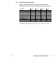
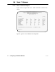
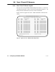
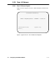
3.8 Your V1 Screen
3.8.1 Your V1 Screen Layout
MODICON MODBUS BRIDGE/MUX – Ver. 1.0
Copyright (c) 1989 MODICON, Inc., Industrial Automation Systems Group
<COMMANDS> [OPTIONS]
<P>PORT NUMBER# 1 2 3 4 [1, 2, 3, 4]
<T>PORT TYPE master slave network slave [m, s, n, x]
<N>Slave Dev Addr – 1 – 230 [1–247]
<B>Baud Rate 9600 1200 2400 9600 [50–19200]
<S>Stop Bits 1 2 1 1 [1, 2]
<R>Parity even none even even [n, o, e]
<M>Mode rtu ascii rtu rtu [a, r]
<Y>Priority 1 2 3 4 [1–4]
<L>Link Timeout – 20 10 600 [1–3000]
<F>Modem Booster – yes yes no [y, n]
MODBUS PORTS CONFIGURATION [V1]
Modbus Plus Address = 24
>>Valid Commands:[V1 V2 V3 V4 P T N B S R M Y L F] Keys:[Enter Esc ?–help]
Active Port 1>> __
Figure 11 Typical V1 Screen: Modbus Ports Configuration