
User`s guide

Configuring the Modbus Models
890 USE 103 00
42
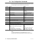
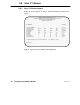
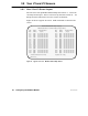
3.6 Your Configuration Commands
&! &!%!&"&!"" $ ""! #
#!" # % !%"
Command Action Range
V Select a configuration screen or Help screen 1 ... 8
P Select a port to be configured 1 ... 4
N Enter a Modbus slave device address 1 ... 247
T Enter the port type M = Master
S = Slave
N = Network
X = Silent Master Network
B Enter the baud rate 50, 300, 1200, 1800, 2000, 2400,
3600, 4800, 7200, 9600, 19200
S Enter the stop bits 1 or 2 (Note 1)
R Enter the parity mode N = None
O = Odd
E = Even
M Enter the communication mode A = ASCII
R = RTU
Y Enter the port priority 1 ... 4
L Enter the link timeout value 1 ... 3000, in multiples of 100 ms
F Enter the modem booster selection Y = Yes
N = No
W Write the configuration parameters to all four ports
D Initialize all four ports with default parameters
? Display Help for the current configuration screen
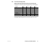
E Enter a Modbus address and five–byte routing path into
the Modbus Address Map table on the V2 or V3 screen.
When you use this command, enter the following:
– the E command
– the table location (1 ... 64) for your entry
– the Modbus address (1 ... 255) to be mapped
– the five bytes of routing (1 ... 255 in each byte).
Entry format:
EYY MM XX XX XX XX XX
where:
E = Modbus Address Map command
YY = location (1 ... 64) in the table
MM = Modbus address (1 ... 255)
XX = each byte (1 ... 255) in the path.
Notes
! " $
""!!""!!#""""!%"""