
User's Manual

74
ENGLISH
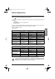
Adjust Menu
This menu can be accessed when the switch is in positions and . Adjustment parameters
can be modified in stop mode OR during operation. Ensure that any changes made during
operation are not dangerous; changes should preferably be made in stop mode.
The list of adjustment parameters is made up of a fixed and a changeable part which varies according to :
-the selected macro-configuration
-the presence of an I/O extension card
-the reassignment of I/O
The following parameters can always be accessed in all the macro-configurations.
(1) In corresponds to the speed controller nominal current indicated in the catalog and on the speed controller
identification label for high torque applications.
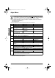
Code Description Adjustment range Factory setting
LL
LL
FF
FF
rr
rr
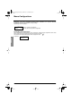
Freq. Ref. - Hz
LSP to HSP –
Appears when control via the display module is activated : LCC parameter in the control menu
AA
AA
CC
CC
CC
CC
dd
dd
EE
EE
CC
CC
Acceleration - s
Deceleration - s
0.05 to 999.9
0.05 to 999.9
3 s
3 s
Acceleration and deceleration ramp times. Ranges 0 to motor nominal frequency (FrS)
AA
AA
CC
CC
22
22
dd
dd
EE
EE
22
22
Accelerate 2 - s
Decelerate 2 - s
0.05 to 999.9
0.05 to 999.9
5 s
5 s
2nd acceleration ramp
2nd deceleration ramp
These parameters can be accessed if the ramp switching threshold (parameter Frt) is other than 0
Hz or if a logic input is assigned to ramp switching.
LL
LL
SS
SS
PP
PP
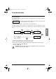
Low Speed - Hz
0 to HSP 0 Hz
Low speed
HH
HH
SS
SS
PP
PP
High Speed - Hz
LSP to tFr 50 / 60 Hz
acc. to the switch
High speed : ensure that this setting is correct for the motor and the application.
FF
FF
LL
LL
GG
GG
Gain - %
0 to 100 20
Frequency loop gain : used to adapt the rapidity of the machine speed transients according to the
dynamics.
For high resistive torque, high inertia or fast cycle machines, increase the gain gradually.
SS
SS
tt
tt
AA
AA
Stability - %
0 to 100 20
Used to adapt the return to steady state after a speed transient according to the dynamics of the
machine.Gradually increase the stability to avoid any overspeed.
II
II
tt
tt
HH
HH
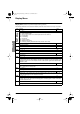
ThermCurrent - A
0.25 to 1.36 In (1) According to controller rating
Current used for motor thermal protection. Set ItH to the nominal current on the motor rating plate.
tt
tt
dd
dd
CC
CC
DC Inj. Time - s 0 to 30 s Cont
0.5 s
DC injection braking time.
If this is increased to more than 30 s, "Cont" is displayed, permanent DC injection.
The injection becomes equal to SdC after 30 seconds.
GP_ATV58_EN.fm Page 74 Mardi, 2. avril 2002 6:09 18