
User manual


Maintenance
33002479 06 07/2008 329
Procedure for
Responding to
an Active LED
Error Indicator
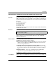
If the Active LED fails to light, the NOE 771 00 module is not communicating with the
backplane . The following procedure describes the steps to perform to respond to
an Active LED error.
Procedure for
Responding to a
Ready LED Error
Indicator
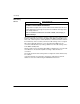
If the Ready LED fails to light, the NOE 771 module has failed internal diagnostic
tests. The following procedure describes the steps to perform.
Procedure for
Responding to a
Link LED Error
Indicator
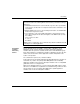
If the Link LED fails to light, the NOE 771 module is not communicating with the
Ethernet hub/switch. The following procedure describes the steps to perform to
respond to a Link LED error.
Step Action
1 Make sure the NOE 771 module and the controller are installed properly.
2 Verify that the controller is working; if it is not, replace it.
3 If neither the new controller nor the NOE 771 module functions, replace the
backplane.
4 Make sure that no more than two network option modules (including NOE, NWM,
NOM, and CRP 811 modules) have been installed in the backplane with a 140 CPU
311 10; not more than six network option modules with a 140 CPU 434 12A,
140 CPU 534 14A, 140 CPU 651 x0, or 140 CPU 671 60.
5 Check the version of the controller executive. You must have version 2.0 or greater
to support the Ethernet module. Earlier versions do not recognize the module.
6 If steps 4 and 5 above check out ok, replace the NOE 771 module.
Step Action
1 Make sure that power has been applied to the backplane.
2 If step 1 checks out ok, replace the NOE 771 module.
Step Action
1 Make sure that the cable has been installed correctly and the module is functioning
properly.
2 Verify that the hub/switch is working properly.
3 If steps 1 and 2 check ok, replace the NOE 771 module.