
User manual


Hot Standby
312
33002479 06 07/2008
Hot Standby Topology
Hot Standby
Interconnection
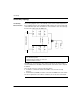
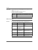
The following diagram shows a Hot Standby system and the relationship between
the 2 redundant systems. Two 140 CPU 671 60 controllers are connected via a link
created with fiber optic cable. The RIOs are connected both to each other (through
the fiber optic cable) and to the RIO drops.
The NOEs are connected to the same switch. Connecting to the same switch is
recommended because the NOEs communicate with each other in order to swap the
IP address.
There are two reasons to connect to the same switch:
z If a failure to communicate between the NOEs occurs, the time to swap
increases.
z To minimize the probability of a failure, connect the two NOEs to the same switch.
The other requirement for the switches is that they are on the same sub-network.
Note: The following three items are required.
1. Two identical systems
2. identical order of modules in each rack
3. identical software revisions
Ethernet Switch
Fiber Optic
Cable
T Connector
Drop
Drop
N
O
E
C
P
6
7
1
R
I
O
N
O
E
C
P
6
7
1
R
I
O
U
U