
User manual

Product Description
33002479 06 07/2008 23
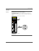
Physical presentation and mounting of standard High End modules
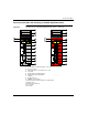
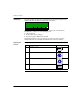
Illustration The figure shows a standard High End module and its components.
1 model number, module description, color code
2 lens cover (open)
3 LCD display (here covered by the lens cover)
4 key switch
5 keypad (with 2 red LED indicators)
6 modbus port (RS-232) (RS-485)
7 USB port
8 Modbus Plus port
9 PCMCIA slots (A and B)
10 LED indicators (yellow) for Ethernet communication
11 Ethernet port
12 battery (user installed)
13 reset button
14 2 screws
MODBUSUSB
ENTERESC MOD
COM
STS
Mac Address
00:00:##:##:##:
140
CPU 65* *0
1
2
3
4
6
7
9
8
10
11
5
13
12
RESTART
MODBUSUSB
ENTERESC MOD
COM
STS
Mac Address
00:00:##:##:##:
140
CPU 651 60S
1
2
3
4
6
7
9
8
10
11
5
13
12
RESTART
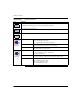
safety processor (red)
14 14
standard processor