
User manual


Transferring Data Using Communication Blocks
152
33002479 06 07/2008
Network Control Block Structures
Summary The structure of the MBP_MSTR control block varies according to the type of network
you are using. Structures for Modbus Plus, TCP/IP Ethernet, and SyMax Ethernet
are described below.
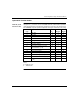
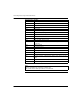
Control Block for
Modbus Plus
Register Contents
CONTROL[1] Indicates an operation that is valid for Modbus Plus
CONTROL[2] Indicates the error status
CONTROL[3] Indicates the length, i.e., the number of data units transferred (max. 100)
CONTROL[4] Indicates MSTR operation-dependent information
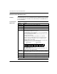
CONTROL[5] Routing register 1: used to specify a destination node during network
transfer (routing path addresses one of five)
Most significant byte: source node address, i.e., the slot for the Modbus
Plus Network Options Module (NOM)
When using the Modbus Plus Port on the CPU, this byte must be set to 0
(regardless of the CPU slot).
Least significant byte: destination node address, i.e., a value that
represents a direct or a bridge address. If there is no bridge, this value
contains the destination node address. If there is a bridge, this value
contains the address of the bridge.
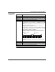
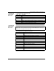
If the NOM is inserted in slot 7 on the module rack, the most significant byte
of routing register 1 looks as follows (value 0x0706):
Most significant byte Slots 1 ... 16
Least significant byte Destination address (binary value between 1 and
64 (normal) or 65 to 255 (extended))
CONTROL[6] Routing register 2, the destination node address (further bridge or Modbus
Plus modules). If addressing in the previous routing register has finished,
the value is set to 0.
CONTROL[7] Routing register 3, similar to routing register 2
CONTROL[8] Routing register 4, similar to routing register 2 (see Routing Register 2)
CONTROL[9] Routing register 5, similar to routing register 2 (see Routing Register 2)
0 0 0 0 0 1 1 1 0 0 0 0 0 1 1 0
most significant
byte
least significant
byte