
User guide

Installin
g
and Confi
g
urin
g
the Module
840 USE 115 00 Version 1.0
21
2.4.1 Selecting the Ethernet Framing Type
You ma
y
choose between Ethernet II and IEEE 802.3, dependin
g
on
y
our s
y
stem.
The default choice is Ethernet II.
If
y
ou are usin
g
the confi
g
uration extension to chan
g
e the framin
g
to IEEE 802.3,
do not for
g
et to desi
g
nate the backplane slot number on the next line. Without the
slot number, the s
y
stem will not record the chan
g
e in framin
g
.
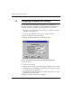
2.4.2 Assigning a Slot Number
To activate the confi
g
uration extension screen,
y
ou must enter the backplane slot
number on the second line. This is the slot where
y
ou have mounted or intend to
mount the Ethernet web embedded serve module. The slots are numbered from left
to ri
g
ht, from one to x.
Note:
If
y
ou do not enter the slot number, the s
y
stem will i
g
nore an
y
other data
y
ou enter on this screen.
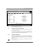
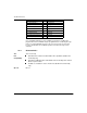
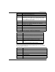
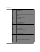
Figure 14 Configuration Extension Screen
modsoft
F1
Hex
P
g
Dn/Up to next/prev Screen
F2 F3 F4 F5 F6 F7 F8 F9
QuitDec Bin Goto
Quantum TCP/IP CONFIG EXT.
Screen 1 / 6
Lev 8
OFF
Ethernet Framin
g
Type:
Internet Address:
Default Gateway Address:
Quantum Backplane Slot:
(B4) : 0 DEC
(B3) : 0 DEC
(B2) : 0 DEC
(B1) : 0 DEC
B4. B3. B2. B1
Note: 000.000.000.000
represents the TCP/IP
Board Default
Internet Address
G4. G3. G2. G1
Note: 000.000.000.000
represents the TCP/IP
Board Default
Gateway Address
(G4) : 0 DEC
(G3) : 0 DEC
(G2) : 0 DEC
(G1) : 0 DEC
SubNetwork MASK: FFFFFF00 HEX
Ethernet II
0