
Technical information


3/16
Modicon M580 automation
platform
Ethernet Modbus/TCP network
Performance
Application response time (continued)
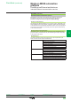
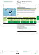
I/O Scanning service response time
The response time RT includes the time between taking account of information from
a remote input and updating the state of a remote output. It includes the processing
time in the PLC.
This response time RT consists of the following parameters:
v TMod In and TMod Out: Response time of the read/written device, excluding the
electrical transition time at the input/output (TMod depends on the device, usually
between 1 and 8 ms)
v TIOS In and TIOS Out: Time between 2 read/write operations on the same device
(0.3 ms
x number of devices scanned), at least equivalent to the congured scan
time
As TIOS is executed in parallel with the PLC cycle, it can be hidden from the
viewpoint of the response time RT.
v Cycle T: PLC scan cycle time
v TNet: Propagation time on the network (depends on the application, but usually
TNet = 0.05 ms at 10 Mbps and 0.005 ms at 100 Mbps)
The response time RT can be estimated using the following 3 formulae:
b RT
min
, minimum response time with TIOS hidden and 1 PLC scan cycle:
b RT
typic
, typical response time with 0.5 TIOS hidden:
b RT
max
, maximum response time with TIOS not hidden:
RT
min
= (TMod In + 0) x TIOS In + (Tnet + N) x cycle T + (0 x TIOS Out) + Tnet + TMod Out
RT
typic
=
(TMod In + 0.5) x TIOS In + (Tnet + N) x cycle T + (0.5 x TIOS Out) + Tnet + TMod Out
RT
max
= TMod In + TIOS In + (Tnet + N) x T cycle + TIOS Out + Tnet + TMod Out
Performance (continued)
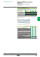
I/O Scanning service response time
Device 1
Device 2
Manager
Hub
Input
Output
CT
RT
Ethernet Modbus/TCP
Response time (RT)
Input
Output
TMod In
TMod Out
TIOS In
TNet
N x Cycle T
TIOS Out
TNet
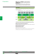
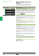
Processors:
page 1/18
I/O architectures:
page 2/2
Software:
page 4/2
Ruggedized Modicon M580
modules: page 5/2
2
1
3
4
5
6
7
8
9
10
2
1
3
4
5
6
7
8
9
10