
Technical information


1/27
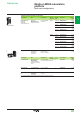
Description
Modicon M580 automation
platform
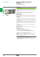
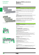
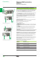
Multi-rack conguration
Modicon M580
Modicon X80 expansion rack
Premium racks
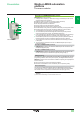
Premium X-bus expansion example
Premium X-bus expansion - making migration as simple as possible
Modicon M580 CPU supports revamping of an existing Premium installation by
replacing the Premium rack 0 (CPU and communication modules) with an M580 rack. It
is also possible to associate TSXRKY4EX/6EX/8EX/12EX Premium racks with X80 I/O
based on an X-bus rack. Most existing congurations are supported. The number of
expansion racks allowed depends on the CPU that is being used:
b BMEP581020, BMEP582020, and BMEP582040 CPUs support a main local rack
and up to 3 expansion racks. If you are using 4, 6, or 8-slot Premium expansion racks,
you may install 2 physical racks at each assigned rack address, allowing up to 6
Premium expansion racks (up to 6 backplanes and 100 m/328.083 ft. between 2
drops).
BMEP583020, BMEP583040, BMEP584020, and BMEP584040 CPUs support a
main local rack with up to 7 expansion racks. If you are using 4, 6, or 8-slot Premium
expansion racks, you may install 2 physical racks at each assigned rack address,
allowing up to 14 Premium expansion racks.
The maximum number of supported X-bus racks is as follows:
b 4 for BMEP581020/20p0
b 8 for BMEP58030p0/40p0
The maximum number of X-bus drops is calculated as follows:
Max number = 1 (CPU rack: BMXXBPpp00 or BMEXBPpp00)
+ ½ number of TSXRKY4/6/8EX racks
+ number of TSXRKY12EX racks
+ number of BMXXBPpp00 racks
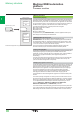
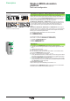
Description
The front panel of the BMXXBE1000 rack expansion module comprises:
5 Retaining screw for locking the module in its slot (at the far right-hand end of the
rack)
6 A display block with 5 LEDs:
b RUN LED (green): module in operation
b COL LED (red): several racks have the same address, or rack address 0 does
not contain the BMEP58ppp0 processor module
b LEDs 0, 1, 2, and 3 (green): rack address 0, 1, 2, or 3
7 A 9-way female SUB-D connector, marked X-bus, for the incoming X-bus cordset
3 connected to the upstream rack, or if it is the rst rack, for the A/ line terminator
included in the TSXTLYEX 4 pack (see page 1/26)
8 A 9-way female SUB-D connector, marked X-bus, for the outgoing X-bus cordset
3 to the downstream rack, or if it is the last rack, for the /B line terminator included
in the TSXTLYEX 4 pack (see page 1/26)
On the right-hand side panel
A ap for accessing the 3 rack addressing micro-switches: 0…3.
Installation rules for BMXXBPppp0 racks: For the rules on how to install racks in
enclosures, see our website www.schneider-electric.com.
5
6
7
8
X-bus
2
1
3
4
5
6
7
8
9
10
2
1
3
4
5
6
7
8
9
10