
Technical information


1/21
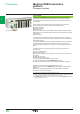
Presentation Modicon M580 automation
platform
Processor modules
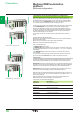
Description of BMEP58pppp processors
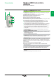
BMEP58pppp processors include :
1 A display block comprising 7 LEDs whose varying combinations provide a quick
diagnostic status of the processor:
b RUN LED (green): processor in operation (program execution)
b ERR LED (red): processor or system detected error
b I/O LED (red): detected I/O module fault
b DL LED (green): rmware download is in progress
b BACKUP LED (red): backup memory (internal or card)
b ETH MS LED (bi-color green/red): indicates the Ethernet port conguration status
b ETH NS LED (bi-color green/red): indicates the Ethernet connection status
2 A mini-B USB port for connecting to a programming terminal
3 An RJ45 Ethernet port that allows diagnosis of Ethernet ports and provides
access to external tools, devices, and distributed I/O devices
5 A slot equipped with a optional SD memory card for application and data storage
(an LED, located behind the door, indicates access to the memory card)
6 A MAC address printed on the front panel of the processor (the last two bytes of
the MAC address are used to calculate the default processor IP address)
7 Two hooks and two screws for mechanical attachment and earthing connection
to backplane
8 Two connectors for electrical connection to a M580 backplane (X-bus only or
Ethernet backplane)
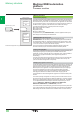
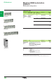
Description of BMEP58
pp20 processors
4 BMEP58pp20 processors have dual RJ45 Ethernet ports for connection to the
distributed equipment (DIO).
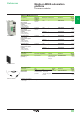
Description of BMEP58pp40 processors
4 BMEP58pp40 processors have dual RJ45 Ethernet ports for connection to the
remote I/O drops (EIO) and distributed equipment (through DRS) (1).
USB terminal port
The USB port 2, offering a useful data rate of 480 Mbps, is compatible with Unity Pro
programming software, OPC Factory Server (OFS), and Magelis HMI terminals (2).
BMEP58 processors can be connected to a USB bus comprising several peripheral
devices. However:
b Only one processor can be connected to the USB bus
b No device on the USB bus can be controlled by the PLC (modem, printer)
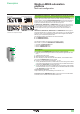
Ethernet backplanes
The new range of Ethernet backplanes feature embedded Ethernet and X-bus
connectivity. With 4, 8, and 12 slots, these two connectors allow the existing M580/
X80 modules to be incorporated into an M580 architecture (see page 3/10).
(1) DRS: Dual Ring Switches. Supported ConneXium switches TCSESM083F23F1/063F2CU1/
063F2CS1.
(2) Please refer to HMI catalogs on www.schneider-electric.com.
BMEP58pppp
1
2
3
4
5
6
7
8
2
1
3
4
5
6
7
8
9
10
2
1
3
4
5
6
7
8
9
10