
Hardware reference guide


Power Supplies
98
35013379 02 October 2007
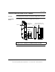
Wiring Diagram
and Timing Chart
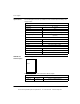
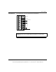
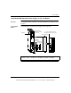
The following figures show the CPS214 wiring diagram (left) and the hold-up
capacitor timing chart (right).
Note:
1. A normally closed relay contact rated at 220 Vac, 6A / 30 Vdc, 5A is available
on terminals 1 and 2 of the power terminal strip. This contact set may be used
to signal input power OFF. The relay will de-energize when input power drops
below 8 Vdc.
2. Tolerance to input interruptions may be increased by adding a ≥ 50 Vdc
electrolytic capacitor between 5 and 6 of the power terminal strip. Refer to the
hold-up capacitor timing chart for capacitor values.
Note: See Power and Grounding Considerations for AC and DC Powered
Systems, p. 776 for power and grounding wiring guidelines and operational
information.
1
2
3
4
5
6
7
}
Power Loss
Alarm
-24 Vdc (Common)
+24 Vdc
+
-
Capacitor
(Optional)
Capacitor Size (millifarads)
Times/ms
Input Voltage
Capacitor
Size
(millifarads)
100
90
80
70
60
50
40
30
20
10
0
20 21 22 23 24 25 26 27 28 29 30
22
10
5.8
4.7
2.2
1
0
4768100
This document provided by Barr-Thorp Electric Co., Inc. 800-473-9123 www.barr-thorp.com