
Hardware reference guide

CableFast Cabling
858
35013379 02 October 2007
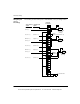
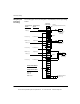
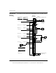
Wiring Diagram
(Chassis
Grounding)
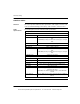
The following shows the wiring for the 140CFK00400 (chassis grounding) module.
S 1
VO 1
CO 1
V 1+
V 1-
1-
S 2
VO 2
CO 2
V 2+
V 2-
2-
S 3
VO 3
CO 3
V 3+
V 3-
3-
S 4
VO 4
CO 4
V 4+
V 4-
4-
GND
RET
V+
Field Side
Connections
Jumper
(See jumper information below)
Field
Device
140 ACO 020 00
Current Out
(Sinking)
Jumper
Field
Device
Field
Device
For 140 ACO 020 00
operation only
140 ACO 020 00
Current Out
(Sourcing)
Jumper
+
-
Shield
I Source 3 (-) Common 3 (-)
Monitor 2 (+) Output 2 (+)
I Source 2 (-) Common 2 (-)
I Source 1 (-) Common 1 (-)
Monitor 1 (+) Output 1 (+)
Monitor 3 (+) Output 3 (+)
I Sink (+) 3
I Sink (+)
I Sink (+) 2
140 AVO 020 00
Voltage Out
140 ACO 020 00
Signals
140 AVO 020 00
Signals
Jumper Part Number
140CFX00110
Jumper Connections
S1 to S2 to S3 to S4
V1- to 1-
CO3 to V3+
This document provided by Barr-Thorp Electric Co., Inc. 800-473-9123 www.barr-thorp.com