
Hardware reference guide


CableFast Cabling
842
35013379 02 October 2007
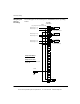
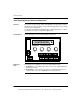
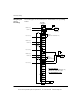
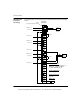
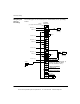
Wiring Diagram
(Chassis
Grounding)
The following figure shows the wiring for the 140CFI00800 (chassis grounding)
module.
S1
1+
1-
V1+
Field Side
Connections
Jumper
(See jumper information below)
Voltage
Source
Current IN
Loop Power Required
+
-
Shield
Module Input 1 (+)
Voltage IN
S2
2+
2-
V2+
S3
3+
3-
V3+
S4
4+
4-
V4+
S5
5+
5-
V5+
S6
6+
6-
V6+
S7
7+
7-
V7+
S8
8+
8-
V8+
GND
RET
V+
4 - 20 mA
Source
4 - 20 mA
Current IN
Instrument Powered
Module Input 1 (-)
Module Input 2 (+)
Module Input 2 (-)
Module Input 3 (+)
Module Input 3 (-)
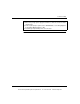
Jumper Part Number
140CFX00110
Jumper Connections
S1 to S2 to S3 to S4 to S5 to S6
to S7 to S8
This document provided by Barr-Thorp Electric Co., Inc. 800-473-9123 www.barr-thorp.com