
Hardware reference guide

Pwr. & Grnding. Guide
776
35013379 02 October 2007
Power and Grounding Considerations for AC and DC Powered Systems
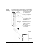
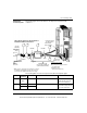
Overview The required power and grounding configurations for AC powered and DC powered
systems are shown in the following illustrations.
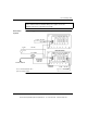
Each backplane shown has its own ground connection; that is, a separate wire
returning to the main grounding point, rather than "daisy chaining" the grounds
between power supplies or mounting plates.
The main grounding point is the local common connection of the panel ground,
equipment ground, and earth grounding electrode.
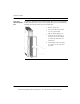
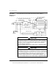
Also shown are power and grounding configurations of AC and DC systems required
for CE compliance. The CE mark indicates compliance with the European Directive
on Electromagnetic Compatibility (EMC) (89/336/EEC) and the Low Voltage
Directive (73/23/EEC). In order to maintain compliance, the Quantum system must
be installed per the installation instructions.
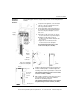
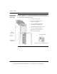
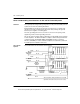
AC Powered
Systems
The following figure shows the AC powered systems.
AC POWER
SOURCE
AC POWER
SOURCE
FUSE
FUSE
AC L
AC N*
AC L
AC N*
PANEL
GROUND
POINT
EQUIPMENT
(CHASSIS)
GROUND
AC POWER
SOURCE
FUSE
AC L
AC N*
EQUIPMENT
(CHASSIS)
GROUND
GROUND
SCREWS
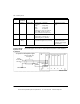
*AC N should be earth grounded. If it is not earth
grounded, it must be fused (refer to local codes).
GROUND
SCREWS
GND
GND
BACKPLANES
PS C
P
U
I/O
or
C
O
M
M
I/O
C
O
M
M
I/O
C
O
M
M
I/O
C
O
M
M
oror or
I/O
or
C
O
M
M
I/O
or
C
O
M
M
I/O
or
C
O
M
M
PS
C
P
U
PS
RED/
GND
RED/
SUM
SUM
This document provided by Barr-Thorp Electric Co., Inc. 800-473-9123 www.barr-thorp.com